Effect
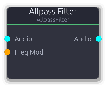
Phase rotation without amplitude change - building block for phasers and reverbs
Second-order allpass filter (RBJ biquad). Passes all frequencies at unity gain but rotates phase around the center frequency.
True stereo with independent filter state per channel. Frequency and Q are smoothed over 128 samples to prevent clicks during modulation.
Freq Mod overrides the Frequency property when connected (ControlFreq, value in Hz, clamped to 20-20,000 Hz). The CV fully replaces the knob value.
Chain several allpass filters in series to build a phaser. Place one in a feedback delay loop for dispersive reverb tails.
Properties
| Name | Type | Default | Range | Help |
|---|
Frequency | Float (Hz) · LogSlider | 1000 | 20 – 20000 | Center frequency where phase rotation is steepest. Overridden by Freq Mod when that port is connected. |
Q | Float · LogSlider | 0.707 | 0.1 – 20 | Controls how sharp the phase transition is around the center frequency. Higher values narrow the transition region. |
Inputs
Audio Audio #0 · required - Stereo audio signal to phase-rotate.
Freq Mod Control (Freq) #1 - Overrides the Frequency property. Value is in Hz (ControlFreq), clamped to 20-20,000 Hz. Smoothed - safe for LFO-driven phaser sweeps.
Outputs
Audio Audio #0 - Phase-rotated stereo audio output.
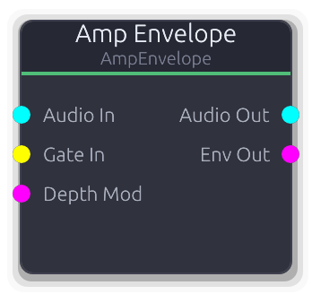
Amplitude envelope - shapes audio volume with a gate-triggered envelope
Combined envelope generator and VCA. Multiplies an audio input by a gate-triggered envelope curve, replacing the Envelope-into-VCA two-node pattern.
The Depth knob scales the envelope level before it is applied to the audio. DepthMod multiplies with Depth (disconnected defaults to 1.0), so effective depth = Depth * DepthMod. The Env output carries the effective envelope value clamped to 0.0-1.0 for downstream modulation. With no audio input connected, Audio Out produces silence but the envelope still advances.
Properties
| Name | Type | Default | Range | Help |
|---|
Shape | Envelope · EnvelopeEditor | Envelope(EnvelopeCurve { curve: Curve { keyframes: [Keyframe { time: 0.0, value: 0.0, in_tangent: 0.0, out_tangent: 0.0 }, Keyframe { time: 0.01, value: 1.0, in_tangent: 0.0, out_tangent: 0.0 }, Keyframe { time: 0.11, value: 0.7, in_tangent: 0.0, out_tangent: 0.0 }, Keyframe { time: 0.31, value: 0.0, in_tangent: 0.0, out_tangent: 0.0 }], range: Normalized }, hold_index: Some(2), phase: Idle, time: 0.0, bridge: None }) | | Editable via the envelope editor widget. Hold index sets the sustain level while the gate is held. |
Depth | Float · Knob | 1 | 0 – 1 | Envelope scaling factor. At 0.0 the envelope has no effect (output = silence since env * 0 = 0). Multiplied with DepthMod when connected. |
Inputs
Audio In Audio #0 · required - Audio signal to shape. When disconnected, Audio Out is silent but the envelope still advances.
Gate In Gate #1 · required - Rising edge triggers attack from curve start; falling edge triggers release from the hold point.
Depth Mod Control (Norm) #2 - Multiplied with the Depth knob. Disconnected defaults to 1.0 (no attenuation).
Outputs
Audio Out Audio #0 - Input audio multiplied by the depth-scaled envelope, per sample.
Env Out Control (Norm) #1 - Effective envelope level (envelope * depth * depth_mod) clamped to 0.0-1.0.
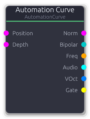
Transport-synced drawn curve for parameter automation
Transport-synced modulation source driven by a user-drawn keyframe curve. Evaluates against the beat timeline to produce parameter automation across six output formats.
The curve position is derived from the transport beat, looping over the configured bar length. Position input overrides the transport playhead when connected (0.0 = curve start, 1.0 = curve end). Depth input scales all outputs (disconnected defaults to 1.0). Frequency outputs use log-scale mapping between FreqMin and FreqMax. VOct is derived from the same frequency mapping relative to middle C (261.63 Hz). Gate goes high when the depth-scaled curve value reaches 0.5.
Properties
| Name | Type | Default | Range | Help |
|---|
Curve | Curve · AutomationCurveEditor | Curve(Curve { keyframes: [Keyframe { time: 0.0, value: 0.0, in_tangent: 0.0, out_tangent: 0.0 }, Keyframe { time: 16.0, value: 0.0, in_tangent: 0.0, out_tangent: 0.0 }], range: Normalized }) | | Drawable keyframe curve. X axis is beats, Y axis is the output value (0.0-1.0 for normalized curves). Keyframe times are rescaled when LengthBars changes. |
Length | Int · SpinBox | 4 | 1 – 64 | Duration of the automation region. Changing this rescales existing keyframe times proportionally. |
Loop | Bool · Toggle | true | | When enabled, the playhead wraps to the start after reaching the end. When disabled, it clamps at the final beat. |
Freq Min Freq Range | Float (Hz) · LogSlider | 20 | 1 – 20000 | Lower bound of the Freq and VOct output range. Curve value 0.0 maps to this frequency. |
Freq Max Freq Range | Float (Hz) · LogSlider | 20000 | 1 – 20000 | Upper bound of the Freq and VOct output range. Curve value 1.0 maps to this frequency. |
Inputs
Position Control (Norm) #0 - Overrides the transport playhead. 0.0 = curve start, 1.0 = curve end. Clamped to 0.0-1.0, then scaled to the beat range to re-evaluate the curve.
Depth Control (Norm) #1 - Multiplies all outputs by this value (clamped to 0.0-1.0). Disconnected defaults to 1.0.
Outputs
Norm Control (Norm) #0 - Depth-scaled curve value (0.0-1.0).
Bipolar Control (Bipolar) #1 - Depth-scaled curve value remapped via (scaled * 2 - 1) to -1.0 to 1.0.
Freq Control (Freq) #2 - Depth-scaled curve value mapped to Hz via log interpolation between FreqMin and FreqMax.
Audio Audio #3 - Depth-scaled curve value as constant mono-to-stereo audio (same value for every sample in the buffer).
VOct V/Oct #4 - V/Oct derived from the same frequency mapping as Freq, relative to middle C (261.63 Hz). Constant per buffer.
Gate Gate #5 - Edge-detected gate high when the depth-scaled curve value is >= 0.5.
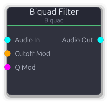
Second-order IIR filter with multiple types
Second-order IIR filter with seven modes: lowpass, highpass, bandpass, notch, peak, low shelf, and high shelf.
True stereo with independent filter state per channel - no crosstalk. All parameters are smoothed over 128 samples to avoid clicks during modulation.
Cutoff Mod overrides the Frequency property when connected (ControlFreq, value in Hz). Q Mod overrides the Q property (ControlNorm, 0.0-1.0 mapped linearly to Q 0.1-20.0). Both CV inputs fully replace the knob value - there is no additive modulation.
Gain only affects Peak, Low Shelf, and High Shelf modes. For LP/HP/BP/Notch it has no effect.
Properties
| Name | Type | Default | Range | Help |
|---|
Type | Enum · Dropdown | 0 | Lowpass / Highpass / Bandpass / Notch / Peak / Lowshelf / Highshelf | LP/HP are the workhorses for tone shaping. Bandpass isolates a frequency region. Notch cuts a narrow band (remove hum, feedback). Peak boosts or cuts around a center frequency (parametric EQ). Shelves boost or cut everything above or below the corner frequency. |
Frequency | Float (Hz) · Knob | 1000 | 20 – 20000 | Center or cutoff frequency. For LP/HP this is the -3 dB point. For bandpass/notch, the center of the affected band. For peak/shelves, where boost or cut is centered. Overridden by Cutoff Mod when that port is connected. |
Q | Float · Knob | 0.707 | 0.1 – 20 | Resonance / bandwidth. 0.707 is Butterworth (flat passband, no ringing). Above ~5 the filter rings audibly - useful for acid-style sweeps. For shelves, Q controls transition slope steepness. Overridden by Q Mod when that port is connected. |
Gain | Float (dB) · Knob | 0 | -24 – 24 | Boost or cut amount. Only active for Peak, Low Shelf, and High Shelf modes - ignored by LP/HP/BP/Notch. Positive values boost, negative values cut. |
Inputs
Audio In Audio #0 · required - Stereo audio to filter.
Cutoff Mod Control (Freq) #1 - Overrides the Frequency property. Value is in Hz (ControlFreq), clamped to 20 Hz through Nyquist. Smoothed - safe for LFO or envelope-driven filter sweeps.
Q Mod Control (Norm) #2 - Overrides the Q property. 0.0 maps to Q 0.1, 1.0 maps to Q 20.0 (linear scaling). Modulating Q with an envelope creates wah-like effects.
Outputs
Audio Out Audio #0 - Filtered stereo audio.
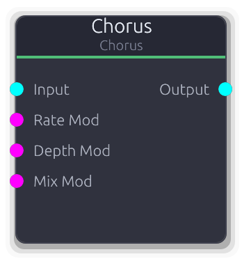
Multi-voice chorus effect with LFO modulation
Multi-voice chorus with LFO-modulated delay lines. Thickens and widens the input by mixing it with detuned, time-varying copies.
Each voice has its own sine LFO with a phase offset evenly distributed across the cycle and a rate that increases by 10% per voice (voice 0 = base rate, voice 1 = 1.1x, etc.). Base delay also staggers by 3 ms per voice. The output is the average of all voices mixed with the dry signal. No feedback path, so the effect stays clean. RateMod CV uses an exponential 0.1..10 Hz mapping; DepthMod maps linearly to 0..20 ms; both replace the property value when connected.
Properties
| Name | Type | Default | Range | Help |
|---|
Voices | Int · SpinBox | 3 | 1 – 8 | Number of delayed chorus voices. Each additional voice adds a staggered LFO and 3 ms of delay offset, thickening the effect. Reinitializes all voices when changed. |
Delay | Float (ms) · Slider | 25 | 5 – 100 | Base delay time for voice 0 before LFO modulation. Each subsequent voice adds 3 ms to this value. |
Depth | Float (ms) · Knob | 3 | 0 – 20 | How far the LFO swings the delay time around the base delay, in milliseconds. |
Rate | Float (Hz) · Knob | 0.5 | 0.1 – 10 | LFO speed for voice 0. Each subsequent voice runs 10% faster (voice 1 = 1.1x, voice 2 = 1.2x, etc.). |
Mix | Float (%) · Slider | 0.4 | 0 – 1 | Crossfade between dry input and the averaged chorus voices. |
Output Gain | Float · Knob | 1 | 0 – 4 | Final gain multiplier applied after the wet/dry mix. |
Inputs
Input Audio #0 - Stereo audio to chorus. Outputs silence when disconnected.
Rate Mod Control (Norm) #1 - ControlNorm 0..1 mapped exponentially to 0.1..10 Hz, replacing the Rate property value when connected.
Depth Mod Control (Norm) #2 - ControlNorm 0..1 mapped linearly to 0..20 ms depth, replacing the Depth property value when connected.
Mix Mod Control (Norm) #3 - ControlNorm 0..1 mapped directly to wet/dry mix, replacing the property value when connected.
Outputs
Output Audio #0 - Stereo output: dry * (1 - mix) + chorus_average * mix, scaled by OutputGain.
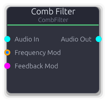
Short delay with feedback for metallic resonances, flanging, and bell tones
Comb filter with feedback, feedforward, and combined modes. A short tuned delay line that reinforces harmonics of its fundamental frequency, producing metallic resonances, bell tones, and Karplus-Strong-style plucks.
True stereo with independent delay buffers per channel. The delay line uses linear interpolation for fractional sample lengths. Frequency, feedback, and mix are all smoothed to prevent clicks.
Frequency Mod accepts both ControlFreq (direct Hz) and V/Oct inputs. V/Oct is relative to the Frequency property (0 = unison, +1 = octave up). If both types are connected, V/Oct takes priority.
Feedback Mod overrides the Feedback property. ControlNorm 0.0-1.0 is scaled to 0.0-0.99.
Damping places a one-pole lowpass in the feedback path. Higher values darken the decay - simulates string damping for physical modeling. Only affects Feedback and Both modes.
Properties
| Name | Type | Default | Range | Help |
|---|
Frequency Comb | Float (Hz) · LogSlider | 440 | 20 – 10000 | Fundamental pitch of the comb resonance. Sets the delay line length as sample_rate / frequency. Overridden by Frequency Mod when that port is connected. |
Feedback Comb | Float · Slider | 0.7 | 0 – 0.99 | Feedback amount. Higher values produce longer, more resonant decays. Capped at 0.99 to prevent runaway oscillation. Overridden by Feedback Mod when that port is connected. |
Mix Comb | Float · Slider | 0.5 | 0 – 1 | Dry/wet balance (0 = fully dry, 1 = fully wet). |
Mode Comb | Enum · Dropdown | 0 | Feedback / Feedforward / Both | Topology. Feedback recirculates the delayed signal for resonant decay. Feedforward mixes delayed with dry (FIR comb, no resonance). Both blends both topologies equally. |
Damping Comb | Float · Slider | 0 | 0 – 1 | One-pole lowpass coefficient in the feedback path. Higher values darken the decay, simulating string damping. At 0.0 the feedback is unfiltered. Only audible in Feedback and Both modes. |
Output Gain | Float · Knob | 1 | 0 – 4 | Output level multiplier applied after all processing. |
Inputs
Audio In Audio #0 · required - Stereo audio input to the comb filter.
Frequency Mod Control (Freq) | V/Oct #1 - Overrides comb frequency. Accepts ControlFreq (direct Hz) or V/Oct (relative to Frequency property, +1 = octave up). V/Oct takes priority when both are connected.
Feedback Mod Control (Norm) #2 - Overrides the Feedback property. ControlNorm 0.0-1.0 is scaled to feedback 0.0-0.99.
Outputs
Audio Out Audio #0 - Filtered stereo audio output.
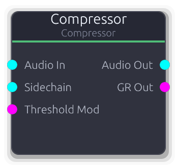
Dynamic range compressor with optional sidechain
Dynamic range compressor with stereo-linked detection. Reduces the volume of signals that exceed the threshold, taming peaks and adding punch.
When the Sidechain input is connected, compression is keyed from that signal (converted to mono) instead of the main audio. The Sidechain takes full priority - there is no blend between internal and external detection. Use this for ducking (kick→bass) and pumping effects.
Threshold Mod overrides the Threshold property when connected. The CV is scaled linearly: 0.0 maps to -60 dB, 1.0 maps to 0 dB. The override is smoothed to prevent clicks.
GR Out reports the maximum gain reduction across L/R channels, normalized so 60 dB of reduction reads as 1.0.
Properties
| Name | Type | Default | Range | Help |
|---|
Threshold Compression | Float (dB) · Slider | -20 | -60 – 0 | Level above which gain reduction begins. Overridden by Threshold Mod when that port is connected. |
Ratio Compression | Float · Knob | 4 | 1 – 20 | How much signals above threshold are attenuated. At 1:1 there is no compression; at 20:1 the compressor approaches limiting. |
Attack Timing | Float (ms) · Knob | 10 | 0.1 – 100 | How fast gain reduction engages when the signal crosses the threshold. Short attack catches transients; long attack lets them punch through. |
Release Timing | Float (ms) · Knob | 100 | 10 – 1000 | How fast gain recovers after the signal drops below threshold. Short release causes pumping; long release smooths dynamics. |
Knee Compression | Float (dB) · Slider | 0 | 0 – 12 | Width of the soft-knee transition around the threshold. At 0.0 the onset is abrupt (hard knee). Higher values ease into compression for more transparent dynamics control. |
Makeup Gain Output | Float (dB) · Knob | 0 | 0 – 24 | Post-compression gain boost to restore perceived loudness. Ignored when Auto Makeup is on. |
Auto Makeup Output | Bool · Toggle | false | 0 – 1 | Automatically compensates output level based on threshold and ratio. Overrides the manual Makeup Gain when enabled. |
Inputs
Audio In Audio #0 · required - Audio signal to compress.
Sidechain Audio #1 - External sidechain signal. When connected, the compressor detects level from this signal (summed to mono) instead of the main audio input. Typical use: feed a kick drum here to duck a bassline.
Threshold Mod Control (Norm) #2 - Overrides the Threshold property. 0.0 maps to -60 dB, 1.0 maps to 0 dB (linear scaling). Smoothed to prevent clicks.
Outputs
Audio Out Audio #0 - Compressed audio output.
GR Out Control (Norm) #1 - Maximum gain reduction across L/R channels. 0.0 = no reduction, 1.0 = 60 dB of reduction. Useful for driving meters or modulating other parameters.
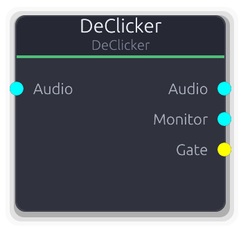
Active click and pop removal via derivative detection and interpolation repair
Active click and pop removal via derivative-based detection and interpolation repair.
Incoming audio is delayed by Lookahead samples through a ring buffer. First- and second-order derivatives are computed per sample; spikes exceeding the Threshold are marked as damaged. If a consecutive damage run exceeds the Sensitivity duration cutoff (Gentle=2, Normal=4, Aggressive=8 samples), it is classified as a musical transient and left untouched. Damaged regions within the cutoff are repaired using Hermite or linear interpolation from the surrounding undamaged context. The Monitor output carries only the removed material (original minus repaired) for audible verification. The Gate output pulses high whenever clicks are detected in a buffer.
Properties
| Name | Type | Default | Range | Help |
|---|
Threshold Detection | Float · Slider | 0.1 | 0.001 – 1 | Derivative spike magnitude that triggers damage marking. Lower values catch subtler clicks but risk false positives on sharp musical transients. The Sensitivity setting provides transient protection as a second line of defense. |
Sensitivity Detection | Enum · Dropdown | 1 | Gentle / Normal / Aggressive | Transient protection level. Controls how many consecutive damaged samples are allowed before the region is classified as a musical transient and passed through unmodified. Gentle=2, Normal=4, Aggressive=8 sample cutoffs. |
Lookahead | Int · SpinBox | 32 | 8 – 128 | Ring buffer size in samples, equal to the output latency. Larger values give the repair algorithm more context for smoother interpolation, at the cost of more delay. Resizing clears all internal state. |
Max Window | Int · SpinBox | 8 | 1 – 32 | Maximum contiguous damaged samples to repair in one region. Regions longer than this pass through unmodified, preventing the interpolator from smearing large sections. |
Mode Repair | Enum · Dropdown | 0 | Hermite / Linear | Interpolation method for repairing damaged samples. Hermite produces C1-continuous splices matching value and slope at boundaries. Linear is faster but lower quality. |
Inputs
Audio Audio #0 · required - Stereo audio to process. Required; produces silence when disconnected. Each channel has independent detection and repair state.
Outputs
Audio Audio #0 - Repaired stereo audio, delayed by Lookahead samples. Outputs silence during the initial priming period.
Monitor Audio #1 - Difference signal (original minus repaired): only the removed click material. Useful for monitoring what the algorithm is cutting.
Gate Gate #2 - Gate high while clicks are detected in the current buffer, low otherwise. Fires edge events, not per-click pulses.
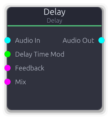
Audio delay with optional time modulation
Stereo delay line with feedback and wet/dry mix. Creates echoes and repeats of the input signal.
Feedback feeds the delayed output back into the delay buffer (input + delayed * feedback), producing decaying repeats. The range is capped at 99% to prevent runaway oscillation, but values above ~90% sustain almost indefinitely. Delay time changes are smoothed over 256 samples to avoid pitch glitches from read-head jumps; connect a slow CV source to the DelayTimeMod port for chorus and vibrato effects. When the DelayTimeMod CV is connected it replaces the property value directly (in seconds), while FeedbackMod and MixMod scale their respective ControlNorm 0..1 ranges into the parameter range.
Properties
| Name | Type | Default | Range | Help |
|---|
Delay Time Delay | Float (s) · Slider | 0.5 | 0.001 – 2 | Time between the dry signal and the first echo. Clamped to the configured max_delay_time (default 2 s). Changes are smoothed over 256 samples. |
Feedback Delay | Float · Knob | 0 | 0 – 0.99 | Fraction of the delayed signal fed back into the delay buffer. Higher values produce more repeats; above ~90% repeats sustain almost indefinitely. |
Mix Delay | Float · Knob | 1 | 0 – 1 | Crossfade between dry input and delayed signal. 0 passes only dry, 1 passes only the delayed (wet) signal. |
Output Gain | Float · Knob | 1 | 0 – 4 | Final gain multiplier applied after the wet/dry mix. |
Inputs
Audio In Audio #0 · required - Stereo audio to delay. Produces silence when disconnected.
Delay Time Mod Control #1 - Delay time in seconds (Control, not ControlNorm). When connected, replaces the DelayTime property value directly.
Feedback Control (Norm) #2 - ControlNorm 0..1 scaled to 0..99% feedback, replacing the property value when connected.
Mix Control (Norm) #3 - ControlNorm 0..1 mapped directly to wet/dry mix, replacing the property value when connected.
Outputs
Audio Out Audio #0 - Stereo output: dry * (1 - mix) + delayed * mix, scaled by OutputGain.
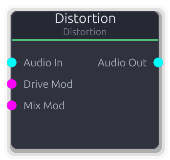
Waveshaping and harmonic distortion with multiple types
Waveshaping distortion with seven selectable algorithms. Drive pushes the signal into saturation; tone and mix shape the final character.
The signal is multiplied by Drive before entering the selected waveshaper. Algorithm differences: HardClip clips at +/-1.0 (harsh, buzzy); SoftClip and Tanh both use soft_clip (smooth saturation); Tube uses asymmetric tube simulation; Fuzz doubles the drive into soft_clip for aggressive saturation; Wavefold folds the signal back at +/-1.0 (adds dense upper harmonics); Bitcrush quantizes to the Bits setting (lo-fi, stepped). The Bits property only affects the Bitcrush algorithm. DriveMod CV maps 0..1 to 1..20x drive; MixMod maps 0..1 directly to wet/dry.
Properties
| Name | Type | Default | Range | Help |
|---|
Type Distortion | Enum · Dropdown | 2 | HardClip / SoftClip / Tanh / Tube / Fuzz / Wavefold / Bitcrush | Selects the waveshaping algorithm. See the node brief for a summary of each algorithm's character. |
Drive Distortion | Float · Knob | 2 | 1 – 20 | Pre-waveshaper gain multiplier. Higher values push more of the signal into the non-linear region of the selected algorithm. |
Mix Distortion | Float (%) · Slider | 1 | 0 – 1 | Crossfade between the clean input and the distorted signal. Useful for parallel distortion blending. |
Tone Distortion | Float (Hz) · LogSlider | 5000 | 1000 – 10000 | Post-distortion lowpass tone filter cutoff. Lower values darken the distorted signal, taming harsh upper harmonics. Not currently wired into the process loop (reserved for future use). |
Output Gain Distortion | Float · Knob | 1 | 0 – 4 | Final output level multiplier applied after the wet/dry mix. Useful for compensating volume changes from heavy distortion. |
DC Blocking Distortion | Bool · Toggle | true | | Enables DC offset removal. Asymmetric algorithms (Tube) can introduce DC bias; this filter removes it. Not currently wired into the process loop (reserved for future use). |
Bits Distortion | Int · SpinBox | 8 | 1 – 16 | Bit depth for the Bitcrush algorithm. Ignored by all other algorithms. Lower values produce harsher quantization noise. |
Inputs
Audio In Audio #0 · required - Stereo audio to distort. Required; produces silence when disconnected.
Drive Mod Control (Norm) #1 - ControlNorm 0..1 mapped linearly to 1..20x drive, replacing the property value when connected.
Mix Mod Control (Norm) #2 - ControlNorm 0..1 mapped directly to wet/dry mix, replacing the property value when connected.
Outputs
Audio Out Audio #0 - Stereo output: clean * (1 - mix) + distorted * mix, then scaled by OutputGain. Per-channel processing.

ADSR envelope generator
General-purpose gate-triggered envelope generator. Outputs the envelope level as a stereo audio signal for use as a VCA control or any parameter modulation source.
The envelope shape is drawn via keyframes and tangents, with an optional hold point that sustains the level while the gate is held. Gate rising edge triggers attack from the start of the curve; falling edge triggers release from the hold point onward. The envelope advances per sample for smooth output.
Properties
| Name | Type | Default | Range | Help |
|---|
Shape | Envelope · EnvelopeEditor | Envelope(EnvelopeCurve { curve: Curve { keyframes: [Keyframe { time: 0.0, value: 0.0, in_tangent: 0.0, out_tangent: 0.0 }, Keyframe { time: 0.01, value: 1.0, in_tangent: 0.0, out_tangent: 0.0 }, Keyframe { time: 0.11, value: 0.7, in_tangent: 0.0, out_tangent: 0.0 }, Keyframe { time: 0.31, value: 0.0, in_tangent: 0.0, out_tangent: 0.0 }], range: Normalized }, hold_index: Some(2), phase: Idle, time: 0.0, bridge: None }) | | Editable via the envelope editor widget. If a hold index is set, the envelope sustains at that keyframe's level while the gate is held. |
Inputs
Gate In Gate #0 · required - Rising edge triggers attack from curve start; falling edge triggers release from the hold point.
Outputs
Env Out Audio #0 - Envelope level as mono-to-stereo audio. Multiply with an audio signal for VCA-style amplitude shaping.
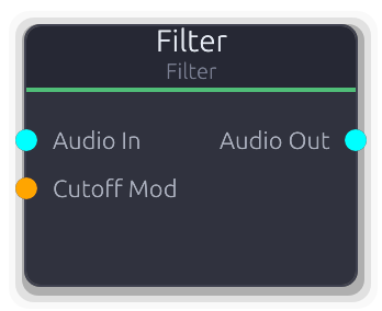
One-pole lowpass filter with cutoff modulation
Simple one-pole lowpass filter. Smoothly attenuates frequencies above the cutoff with a gentle 6 dB/octave slope.
True stereo with independent filter state per channel. The cutoff is smoothed to prevent clicks during modulation.
Cutoff Mod overrides the Cutoff property when connected (ControlFreq, value in Hz). The CV fully replaces the knob value - there is no additive modulation. When disconnected, the property value is used.
For steeper filtering or resonance control, use the Biquad Filter.
Properties
| Name | Type | Default | Range | Help |
|---|
Cutoff Filter | Float (Hz) · LogSlider | 1000 | 20 – 20000 | Lowpass cutoff frequency. Overridden by Cutoff Mod when that port is connected. |
Inputs
Audio In Audio #0 · required - Stereo audio signal to filter.
Cutoff Mod Control (Freq) #1 - Overrides the Cutoff property. Value is in Hz (ControlFreq). Smoothed - safe for LFO-driven sweeps. When disconnected, the Cutoff property value is used.
Outputs
Audio Out Audio #0 - Lowpass-filtered stereo audio output.
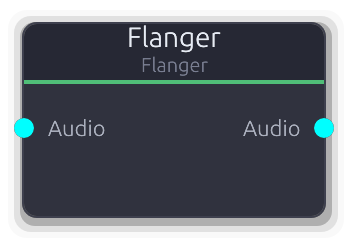
Short modulated delay with feedback - classic flanger effect
Classic flanger effect. A short delay modulated by a sine LFO and fed back into itself, producing a sweeping comb-filter tone.
The modulated delay time equals base_delay * (1 + LFO * depth), clamped to the 10 ms hardware maximum. Feedback feeds the delayed output back into the delay buffer (input + delayed * feedback). Negative feedback values invert the signal before feeding back, shifting the comb peaks to produce a hollower, more nasal character. No CV modulation inputs; use the property controls. No parameter smoothing, so abrupt changes to delay or rate may click.
Properties
| Name | Type | Default | Range | Help |
|---|
Rate | Float (Hz) · LogSlider | 0.3 | 0.01 – 10 | Internal sine LFO speed controlling the delay sweep. |
Depth | Float · Slider | 0.7 | 0 – 1 | LFO modulation depth as a multiplier of the base delay. At 0 the delay is static; at 1 it swings from 0 to 2x the base delay. |
Delay | Float (ms) · Slider | 3 | 0.1 – 10 | Center delay time around which the LFO modulates. Shorter values produce higher-pitched metallic resonances. |
Feedback | Float · Slider | 0.5 | -0.95 – 0.95 | Fraction of the delayed output fed back into the delay buffer. Positive values reinforce comb peaks; negative values invert the feedback, shifting peaks to notches for a hollower timbre. |
Mix | Float · Slider | 0.5 | 0 – 1 | Crossfade between dry input and flanged signal. |
Output Gain | Float · Knob | 1 | 0 – 4 | Final gain multiplier applied after the wet/dry mix. |
Inputs
Audio Audio #0 · required - Stereo audio to flange. Required; produces silence when disconnected.
Outputs
Audio Audio #0 - Stereo output: dry * (1 - mix) + delayed * mix, scaled by OutputGain.
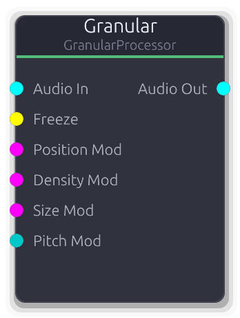
Live granular effects processor with freeze and pitch control
Live granular effects processor. Records audio into a circular buffer and spawns overlapping grains that read back from configurable positions with pitch shifting and stereo spread.
Grains are scheduled at the Density rate (Hz). Each grain reads from Position (0 = most recent, 1 = oldest) in the circular buffer, with Jitter randomizing position, size, and pitch per grain. Grains use linear interpolation for fractional read positions and a morphable window envelope (Texture: 0 = rectangular, 0.5 = Hann, 1.0 = narrow Gaussian). The Freeze gate stops buffer recording so grains read from a frozen snapshot; unfreezing resumes recording from where the write head left off. Active grains are averaged (not summed) when more than one is playing. CV inputs are additive offsets to the property values, not replacements. PitchMod is ControlBipolar and scales by the full +/-24 semitone range.
Properties
| Name | Type | Default | Range | Help |
|---|
Buffer | Float (s) · Knob | 4 | 1 – 8 | Circular buffer duration. Determines how far back in time grains can read. The actual buffer is pre-allocated at 8 seconds; this setting limits the usable range. |
Density | Float (Hz) · Knob | 10 | 0.5 – 100 | Grain spawn rate. Higher values produce denser, more continuous textures. Grains beyond MaxGrains are skipped. |
Size | Float (ms) · Knob | 50 | 5 – 500 | Individual grain duration. Longer grains produce smoother textures; shorter grains are more percussive and rhythmic. Subject to Jitter randomization per grain. |
Position | Float · Knob | 0 | 0 – 1 | Where grains read from in the circular buffer. 0 reads from the most recently recorded audio; 1 reads from the oldest. Subject to Jitter randomization per grain. |
Pitch | Float (semi) · Knob | 0 | -24 – 24 | Grain playback pitch offset. Converted to a playback rate via 2^(semitones/12). Subject to Jitter randomization per grain (+/-2 semitones at full jitter). |
Spread | Float · Knob | 0.3 | 0 – 1 | Stereo pan randomization per grain. Each grain gets a random pan position within +/-Spread, using constant- power panning. At 0 all grains are centered. |
Jitter | Float · Knob | 0.1 | 0 – 1 | Per-grain randomization amount applied to position, size, and pitch. At 0 all grains are identical; at 1 position varies by +/-1.0, size varies by +/-100%, and pitch varies by +/-2 semitones. |
Max Grains | Int · SpinBox | 16 | 1 – 64 | Maximum simultaneous grains. When the pool is full, new grains from the density scheduler are skipped until existing grains expire. |
Texture | Float · Knob | 0.5 | 0 – 1 | Window envelope shape morphing. Rectangular windows (texture=0) let full amplitude through but click at grain boundaries. Hann (0.5) is a smooth default. Narrow Gaussian (1.0) concentrates energy at grain centers. |
Output Gain | Float · Knob | 1 | 0 – 4 | Final gain multiplier applied to the averaged grain output. |
Inputs
Audio In Audio #0 · required - Live stereo audio, continuously recorded into the circular buffer (unless frozen). Required; produces silence when disconnected.
Freeze Gate #1 · required - Rising edge freezes buffer recording; falling edge resumes. Grains continue reading from the frozen buffer while frozen.
Position Mod Control (Norm) #2 · required - ControlNorm 0..1 added to the Position property value. The sum is clamped to 0..1.
Density Mod Control (Norm) #3 · required - ControlNorm 0..1 scaled by the full density range (0.5..100 Hz) and added to the property value.
Size Mod Control (Norm) #4 · required - ControlNorm 0..1 scaled by the full size range (5..500 ms) and added to the property value.
Pitch Mod Control (Bipolar) #5 · required - ControlBipolar -1..1 scaled by the full pitch range (+/-24 semitones) and added to the property value.
Outputs
Audio Out Audio #0 - Averaged grain output, scaled by OutputGain. No dry signal is mixed in; use an external mixer for dry/wet blending.
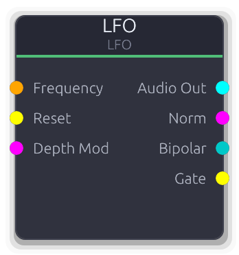
Low-frequency oscillator for modulation
Low-frequency oscillator for cyclic modulation of any parameter. Produces synchronized outputs in multiple formats: audio, normalized, bipolar, and gate.
FrequencyMod overrides the Frequency knob entirely when connected (it does not add to it). DepthMod overrides the Depth knob's smoother target when connected. All outputs are scaled by the effective depth. The Gate output goes high on the positive half of the waveform cycle.
Properties
| Name | Type | Default | Range | Help |
|---|
Frequency | Float (Hz) · LogSlider | 5 | 0.01 – 20 | Oscillation speed. Ignored when FrequencyMod is connected. |
Depth | Float · Knob | 0.5 | 0 – 1 | Output amplitude scaling. Smoothed to prevent clicks. Overridden when DepthMod is connected. |
Waveform | Enum · Dropdown | 0 | Sine / Square / Sawtooth / Triangle | Oscillator waveshape. Sine and triangle are smooth; square and sawtooth have hard edges. |
Inputs
Frequency Control (Freq) #0 - Overrides the Frequency knob with an external signal in Hz. Uses the raw control value directly.
Reset Gate #1 - Rising edge resets phase to zero for tempo sync or retriggering.
Depth Mod Control (Norm) #2 - Overrides the Depth knob's smoother target. Smoothing still applies to avoid clicks.
Outputs
Audio Out Audio #0 - Bipolar waveform as stereo audio, scaled by depth. Per-sample generation.
Norm Control (Norm) #1 - Last sample of the buffer remapped to 0.0-1.0, scaled by depth.
Bipolar Control (Bipolar) #2 - Last sample of the buffer as bipolar control, scaled by depth.
Gate Gate #3 - Edge-detected gate high when the depth-scaled waveform is positive.
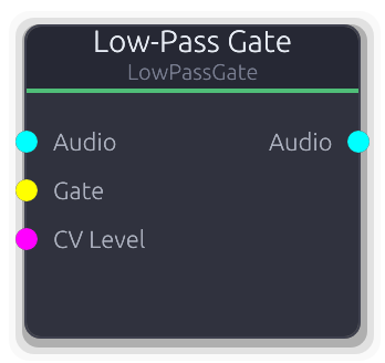
Combined VCA + lowpass with vactrol-style decay - Buchla LPG
Combined VCA and lowpass filter with vactrol-style decay. The Buchla signature sound: strike it with a gate and it opens briefly, then closes with an organic, woody decay.
A gate rising edge snaps the internal vactrol level to 1.0. It then decays exponentially, with a sqrt curve applied to model the fast-open, slow-close photoresistor response. The CV Level input can also drive the vactrol; it takes the maximum of the current vactrol level and the CV value, so holding CV high keeps the gate open. VCA Amount controls how much the vactrol affects amplitude (0 = unity gain, 1 = full gating). LPF Amount controls cutoff sweep depth; the cutoff tracks the vactrol level on a log scale from 20 Hz to just below Nyquist. With both VCA and LPF at 1.0 the sound starts bright and loud, then dims and quiets together.
Properties
| Name | Type | Default | Range | Help |
|---|
Decay | Float (ms) · LogSlider | 200 | 10 – 2000 | Vactrol decay time constant. Short values give percussive plucks; long values let the gate ring out. The actual envelope is exponential with a sqrt curve, so the perceived tail is longer than the time constant. |
Resonance | Float · Knob | 0 | 0 – 0.95 | Resonance emphasis at the sweeping cutoff frequency. Adds a peak that accentuates the filter sweep as the vactrol decays. |
VCA Balance | Float · Slider | 0.5 | 0 – 1 | How much the vactrol level controls amplitude. At 0 the signal passes at unity gain regardless of the vactrol; at 1 amplitude tracks the vactrol fully. |
LPF Balance | Float · Slider | 0.5 | 0 – 1 | How much the vactrol level controls filter cutoff depth. At 0 the cutoff stays near Nyquist (effectively bypassed); at 1 the cutoff sweeps the full 20 Hz to Nyquist range with the vactrol. |
Inputs
Audio Audio #0 · required - Stereo audio to pass through the gate. Required; produces silence when disconnected.
Gate Gate #1 - Gate signal. Each rising edge resets the vactrol level to 1.0, starting a fresh decay. Has no effect while the vactrol is already at 1.0.
CV Level Control (Norm) #2 - ControlNorm 0..1 that holds the vactrol open. The vactrol level becomes max(decaying_level, cv), so holding CV high prevents the gate from closing.
Outputs
Audio Audio #0 - Audio shaped by the combined VCA gain and lowpass filter, both driven by the vactrol level.
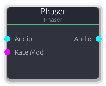
Multi-stage allpass sweep - classic phaser effect
Multi-stage phaser effect. Chains allpass filters whose center frequency sweeps via an internal LFO, carving moving notches through the spectrum.
The LFO sweeps logarithmically between MinFreq and MaxFreq, scaled by Depth. The allpass chain output feeds back into its own input (input + chain_output * feedback) to deepen the notches. More stages produce more notches; the step size is 2 so the count is always even. RateMod CV scales the base rate multiplicatively: effective_rate = rate * (1 + cv * 4), so at CV=1.0 the rate is 5x faster.
Properties
| Name | Type | Default | Range | Help |
|---|
Rate | Float (Hz) · LogSlider | 0.5 | 0.01 – 10 | Internal sine LFO speed controlling the allpass frequency sweep. Multiplied by the RateMod CV when connected. |
Depth | Float · Slider | 0.8 | 0 – 1 | How far the LFO sweeps through the MinFreq..MaxFreq range. At 0 the frequency is pinned to MinFreq; at 1 it sweeps the full range. |
Feedback | Float · Slider | 0.5 | 0 – 0.95 | Feeds the allpass chain output back into its input, making the notches deeper and more resonant. |
Stages | Int · SpinBox | 4 | 2 – 12 | Number of allpass stages. More stages carve more notches into the spectrum. Steps by 2 (always even). Resizes the internal filter state when changed. |
Mix | Float · Slider | 0.5 | 0 – 1 | Crossfade between dry input and the allpass-filtered signal. |
Output Gain | Float · Knob | 1 | 0 – 4 | Final gain multiplier applied after the wet/dry mix. |
Inputs
Audio Audio #0 · required - Stereo audio to phase. Required; produces silence when disconnected.
Rate Mod Control (Norm) #1 - ControlNorm 0..1 that multiplies the base rate: effective = rate * (1 + cv * 4). At cv=0 uses the base rate; at cv=1 the rate is 5x faster.
Outputs
Audio Audio #0 - Stereo output: dry * (1 - mix) + allpass_chain * mix, scaled by OutputGain.
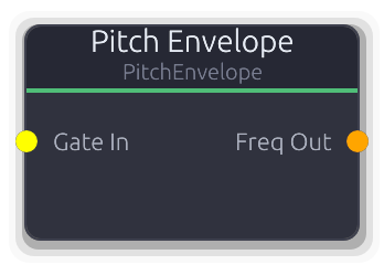
Gate-triggered frequency sweep for percussive pitch control
Gate-triggered frequency sweep for percussive pitch effects. Outputs ControlFreq directly, eliminating the need for an Envelope into a frequency mapper chain.
The drawn curve maps 0.0 to StartFreq and 1.0 to EndFreq using log-space interpolation for perceptually even pitch movement. The default curve fires a fast attack to EndFreq then decays back to StartFreq with no hold point (fire-and-forget). The envelope is sampled once per buffer, not per sample.
Properties
| Name | Type | Default | Range | Help |
|---|
Start Freq Frequency | Float (Hz) · LogSlider | 55 | 20 – 20000 | Frequency when the envelope curve is at 0.0. |
End Freq Frequency | Float (Hz) · LogSlider | 300 | 20 – 20000 | Frequency when the envelope curve is at 1.0. |
Shape | Envelope · EnvelopeEditor | Envelope(EnvelopeCurve { curve: Curve { keyframes: [Keyframe { time: 0.0, value: 0.0, in_tangent: 0.0, out_tangent: 8.0 }, Keyframe { time: 0.001, value: 1.0, in_tangent: 0.0, out_tangent: -2.0 }, Keyframe { time: 0.05, value: 0.0, in_tangent: -1.0, out_tangent: 0.0 }], range: Normalized }, hold_index: None, phase: Idle, time: 0.0, bridge: None }) | | Defines sweep shape and timing. Curve value 0.0 maps to StartFreq, 1.0 maps to EndFreq. Default is a fast attack then exponential decay with no hold point. |
Inputs
Gate In Gate #0 · required - Rising edge fires the pitch sweep from curve start. Falling edge triggers release if a hold point is set.
Outputs
Freq Out Control (Freq) #0 - Frequency in Hz, log-interpolated between StartFreq and EndFreq based on the envelope curve value.
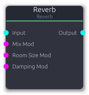
Room simulation reverb with Schroeder algorithm
Schroeder reverb with true stereo output. Simulates room reflections from tight rooms to vast halls.
The input is downmixed to mono before entering the reverb engine. Parallel damped comb filters produce late reflections, then series allpass filters add diffusion. Left and right channels use decorrelated delay lines for stereo imaging, controlled by the Width parameter. Pre-delay inserts a fixed gap between the dry sound and the onset of the reverb tail; changing pre-delay or room size rebuilds the internal filter network (may click during live adjustment). CV inputs for room size, damping, and mix all replace the property value directly via smoothers.
Properties
| Name | Type | Default | Range | Help |
|---|
Room Size | Float · Knob | 0.5 | 0 – 1 | Controls comb filter delay lengths and feedback, affecting both perceived room size and decay time. Changing this value rebuilds the filter network. |
Damping | Float · Knob | 0.5 | 0 – 1 | High-frequency absorption inside the comb filters. Higher values darken the reverb tail, simulating soft or absorptive surfaces. |
Pre-Delay | Float (ms) · Slider | 0 | 0 – 100 | Fixed delay before the reverb tail begins. Separates the dry transient from the wet reflections, useful for preserving clarity on percussive sources. Changing this value rebuilds the filter network. |
Diffusion | Float · Knob | 0.5 | 0 – 1 | Allpass filter gain controlling how much the reflections are smeared in time. Higher values spread reflections more evenly; lower values leave audible echo clusters. |
Width | Float · Knob | 1 | 0 – 1 | Stereo spread of the wet reverb output. At 0 the left and right wet signals are summed to mono; at 1 the decorrelated delay lines are fully separated. |
Mix | Float (%) · Slider | 0.3 | 0 – 1 | Crossfade between dry input and reverb tail. Default is 0.3 for a send-style balance. |
Output Gain | Float · Knob | 1 | 0 – 4 | Final gain multiplier applied after the wet/dry mix. |
Inputs
Input Audio #0 - Stereo audio input. Both channels are summed to mono before entering the reverb engine. Outputs silence when disconnected (the reverb tail still decays naturally).
Mix Mod Control (Norm) #1 - ControlNorm 0..1 mapped directly to wet/dry mix, replacing the property value when connected.
Room Size Mod Control (Norm) #2 - ControlNorm 0..1 mapped directly to room size, replacing the property value when connected. Smoothed, does not trigger filter rebuild.
Damping Mod Control (Norm) #3 - ControlNorm 0..1 mapped directly to damping, replacing the property value when connected.
Outputs
Output Audio #0 - Stereo reverb output with decorrelated L/R channels, mixed with the dry input per the Mix setting.
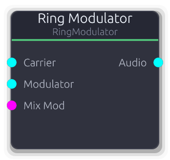
Carrier × modulator ring modulation with dry/wet mix
Ring modulator -- multiplies a carrier and modulator signal together, producing sum and difference frequencies for inharmonic, bell-like, or robotic timbres.
Both Carrier and Modulator audio inputs are required; disconnecting either silences the output. The wet signal is carrier * modulator (per-channel); the Mix control crossfades between the dry carrier and the ring-modulated result. Unlike SignalMath's Multiply mode, this node provides explicit carrier/modulator labeling and a dedicated dry/wet mix.
Properties
| Name | Type | Default | Range | Help |
|---|
Mix | Float · Slider | 1 | 0 – 1 | Crossfade between the dry carrier and the ring-modulated signal. At 0 the carrier passes unaffected; at 1 only the product is heard. |
Output Gain | Float · Knob | 1 | 0 – 4 | Final gain multiplier applied after the wet/dry mix. |
Inputs
Carrier Audio #0 · required - Primary audio signal. Used as the "dry" signal for the Mix crossfade. Required; silences output when disconnected.
Modulator Audio #1 · required - Audio signal multiplied with the carrier per-channel. Required; silences output when disconnected.
Mix Mod Control (Norm) #2 - ControlNorm 0..1 mapped directly to wet/dry mix, replacing the property value when connected. Clamped to 0..1.
Outputs
Audio Audio #0 - Stereo output: carrier * (1 - mix) + (carrier * modulator) * mix, scaled by OutputGain.
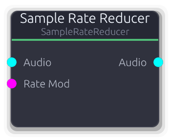
Lo-fi aliasing effect - reduces effective sample rate
Lo-fi aliasing effect that reduces the effective sample rate by holding each input sample for multiple output cycles.
Uses a phase accumulator: the input is sampled only when the phase wraps past 1.0, then that value is held until the next wrap. This creates staircase artifacts and harsh aliasing distinct from bitcrushing. The RateMod CV scales linearly from 100 Hz (at cv=0) to the configured target rate (at cv=1), replacing the property value when connected.
Properties
| Name | Type | Default | Range | Help |
|---|
Rate | Float (Hz) · LogSlider | 8000 | 100 – 44100 | Target effective sample rate. Lower values hold each sample longer, producing more aliasing and lo-fi character. |
Inputs
Audio Audio #0 · required - Stereo audio to decimate. Required; produces silence when disconnected.
Rate Mod Control (Norm) #1 - ControlNorm 0..1 mapped linearly from 100 Hz (at 0) to the configured target rate (at 1). Replaces the property value when connected.
Outputs
Audio Audio #0 - Stereo output with sample-and-hold decimation applied.
Independent attack and sustain gain reshaping
Reshapes the attack and sustain portions of a signal independently. Boost the attack to add punch, or pull it back to soften transients.
Uses dual envelope followers per channel: a fast follower (~1 ms attack) that catches transients, and a slow follower (4x the Speed setting) that tracks the sustain level. The difference (fast - slow) isolates the transient component. Each sample's gain is a weighted blend of the Attack and Sustain gains based on the transient ratio. Both gain controls are in dB and converted to linear internally. No CV modulation inputs. Speed affects both the fast follower's release and the slow follower's time constant, so increasing it widens the transient detection window.
Properties
| Name | Type | Default | Range | Help |
|---|
Attack | Float (dB) · Slider | 0 | -12 – 12 | Gain applied to detected transient peaks. Positive values make attacks punchier; negative values soften them. |
Sustain | Float (dB) · Slider | 0 | -12 – 12 | Gain applied to the sustained body of the signal (non- transient portions). Positive values boost the body; negative values thin it out. |
Speed | Float (ms) · Slider | 20 | 5 – 100 | Detection window controlling how long a peak must persist before it is classified as sustain rather than a transient. Also sets the slow follower to 4x this value. Shorter values isolate only the sharpest transients. |
Output Gain | Float · Knob | 1 | 0 – 4 | Final gain multiplier applied after transient/sustain shaping. |
Inputs
Audio Audio #0 · required - Stereo audio to reshape. Required; produces silence when disconnected. Each channel is processed independently with its own envelope followers.
Outputs
Audio Audio #0 - Stereo audio with reshaped transient and sustain gain, scaled by OutputGain.
Channel vocoder - spectral envelope transfer from modulator to carrier
Channel vocoder that transfers the spectral envelope of a modulator onto a carrier signal, producing the iconic robot-voice effect.
The modulator (voice, drums) is split into frequency bands; an envelope follower on each band extracts how loud that frequency region is. Those envelopes are applied to the same bands of the carrier (synth, noise), so the carrier "speaks" with the modulator's tonal shape.
Both inputs are required. Without a modulator the output is silence because the envelope followers produce zero. A carrier alone produces nothing - the modulator's envelope gates it.
Sibilance detection measures the energy ratio of the top quarter of bands to the total. When high-frequency energy dominates, unfiltered modulator audio is blended into the output, preserving consonant sounds like "s", "t", and "sh" that the band filters would otherwise smear.
The Freq Tilt curve applies per-band gain using a log-frequency axis (20 Hz to 20 kHz). Each band's center frequency is mapped onto this curve. A rising curve brightens the output; a falling curve warms it.
Properties
| Name | Type | Default | Range | Help |
|---|
Bands | Int · Slider | 16 | 4 – 32 | Number of frequency analysis bands. More bands give finer spectral resolution at higher CPU cost. 16 is a good default for speech. |
Low Freq | Float (Hz) · Knob | 80 | 20 – 500 | Lowest band center frequency. Bands are log-spaced between this and High Freq. Raise to ignore low rumble; lower for sub-bass content. |
High Freq | Float (Hz) · Knob | 8000 | 2000 – 16000 | Highest band center frequency. Raise for more air and presence; lower if the carrier has little content above 8 kHz. |
Attack | Float (ms) · Knob | 5 | 0.1 – 50 | Envelope follower attack time per band. Fast attack + slow release gives the classic talk-box articulation. Slow attack mushes consonants. |
Release | Float (ms) · Knob | 20 | 1 – 200 | Envelope follower release time per band. Longer release smooths transitions between syllables. Too fast and the output chatters. |
Q | Float · Knob | 5 | 1 – 20 | Bandpass filter resonance. Higher Q narrows each band for more precise spectral transfer but adds resonant coloring. Lower Q widens bands for a smoother, less articulate result. |
Noise Gate | Float · Knob | 0 | 0 – 1 | Zeroes bands whose envelope falls below this threshold. Reduces noise and bleed between words. At 0.0 the gate is disabled. |
Sibilance | Float · Knob | 0 | 0 – 1 | Blends unfiltered modulator audio when the top quarter of bands dominate the total energy. Preserves "s", "t", "sh" consonants that bandpass filtering would smear. At 0.0 sibilance bypass is off. |
Freq Tilt | Curve · BandCurveEditor | Curve(Curve { keyframes: [Keyframe { time: 0.0, value: 1.0, in_tangent: 0.0, out_tangent: 0.0 }, Keyframe { time: 1.0, value: 1.0, in_tangent: 0.0, out_tangent: 0.0 }], range: Normalized }) | | Per-band gain curve drawn on a log-frequency axis. Each band's center frequency is evaluated against this curve. A rising shape brightens the output; a falling shape adds warmth. Defaults to flat (all bands equal). |
Output Gain | Float · Knob | 1 | 0 – 4 | Output level multiplier applied after all processing. |
Inputs
Carrier Audio #0 · required - Harmonically rich signal (sawtooth, noise, chord) whose spectral content is shaped by the modulator. This is what you hear.
Modulator Audio #1 · required - Signal whose spectral envelope controls the carrier (voice, drums). Without a modulator the output is silence.
Outputs
Audio Audio #0 - Carrier audio shaped by the modulator's spectral envelope, scaled by Freq Tilt and Output Gain.
Fractal Brownian Motion noise - organic modulation source
Fractal Brownian Motion noise source for organic, evolving modulation. Sums multiple octaves of smooth value noise to produce natural-feeling movement.
Audio and control outputs are the raw fBm value scaled by Amplitude. RateMod maps 0.0-1.0 to a 1x-4x rate multiplier (exponential via 2^(mod*2)); disconnected defaults to 1x. Gate rising edge jumps to a new region of the noise field (each retrigger lands at a different position). The Gate output goes high on the positive half of the noise signal.
Properties
| Name | Type | Default | Range | Help |
|---|
Rate | Float (Hz) · LogSlider | 1 | 0.01 – 100 | Base traversal speed through the noise field. Scaled by RateMod when connected. |
Octaves | Int · Slider | 4 | 1 – 8 | Number of noise layers summed together. More octaves add finer, faster detail on top of the base motion. |
Persistence | Float · Slider | 0.5 | 0 – 1 | Amplitude decay per octave. Low values fade higher octaves quickly, keeping the output smooth. |
Lacunarity | Float · Slider | 2 | 1.5 – 3 | Frequency multiplier between successive octaves. Higher values space octaves further apart in frequency. |
Amplitude | Float · Knob | 1 | 0 – 1 | Scales the raw fBm value before all outputs. |
Seed | Int · Slider | 42 | 0 – 9999 | Random seed for the noise field. Different seeds produce entirely different patterns. |
Inputs
Gate Gate #0 - Rising edge jumps to a new region of the noise field. Each retrigger lands at a different position, so rapid retriggering does not freeze the output.
Rate Mod Control (Norm) #1 - Multiplies the Rate knob via 2^(mod*2). At 0.0 = 1x, at 1.0 = 4x. Disconnected defaults to 1x.
Outputs
Audio Out Audio #0 - Noise as mono-to-stereo audio, bipolar and scaled by Amplitude. Per-sample generation.
Norm Control (Norm) #1 - Last sample of the buffer remapped from bipolar to 0.0-1.0.
Bipolar Control (Bipolar) #2 - Last sample of the buffer clamped to -1.0 to 1.0.
Control Control #3 - Raw noise value without clamping, for custom downstream scaling.
Gate Gate #4 - Edge-detected gate high when the amplitude-scaled noise value is positive.
MIDI
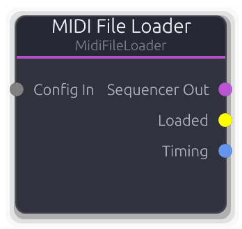
Loads ABC notation files and converts to sequencer configuration. Supports file paths or raw ABC text.
Loads ABC notation and produces a MidiSequencer on its output for downstream playback.
Accepts an AbcSource (file path or raw text), a ConstantValue file path, or a full AbcFileLoaderConfig via the Config input. When no Config input is connected, falls back to the embedded source property. Parsing only runs when the config changes (detected via a string key). The Sequencer Out streams the cached MidiSequencer every frame. Timing Out carries BPM and time signature extracted from the ABC notation.
Inputs
Config In Data(Unknown) #0 - Accepts AbcSource, ConstantValue::FilePath, or full AbcFileLoaderConfig. Overrides the embedded source property when connected.
Outputs
Sequencer Out Data(Sequence) #0 - Cached MidiSequencer data, streamed every frame. Connect to a Sequencer or Sequencer Editor.
Timing Data(Timing) #1 - BPM and time signature extracted from the ABC notation. Defaults to 4/4 if not specified in the source.
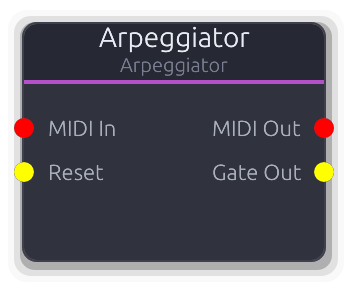
Converts held MIDI notes into arpeggiated patterns
Turns held MIDI chords into rhythmic arpeggiated patterns using an internal sample-accurate clock.
Feed it notes and it cycles through them at a configurable rate with selectable direction (up, down, up-down, random), octave range, gate length, and swing. Uses NoteOn velocity=0 as NoteOff. The internal clock derives step timing from the Rate property; swing delays every other step by a fraction of the step duration. Gate length determines when each note-off fires within the step. The Reset input resets the arpeggiator to the first note and kills any currently sounding note. With Latch enabled, notes remain in the pattern even after key release -- new notes replace the latched set. All output MIDI is on channel 1.
Properties
| Name | Type | Default | Range | Help |
|---|
Rate Timing | Float (Hz) | 8 | 0.1 – 20 | Internal clock frequency. Determines step timing together with swing. |
Pattern Pattern | Enum | 0 | Up / Down / Up-Down / Random / As Played / Chord | Arpeggio direction: Up, Down, Up-Down, Random, etc. |
Octaves Pattern | Int | 1 | 1 – 4 | Repeats the held notes across this many octaves. |
Gate Length Timing | Float (%) | 0.75 | 0.1 – 0.95 | Fraction of each step that the gate/note stays on. Note-off fires at this fraction of the step duration. |
Swing Timing | Float (%) | 0 | 0 – 0.75 | Delays every other step by this fraction of the step duration. Creates a shuffle feel. |
Latch Control | Bool | false | | When enabled, notes stay in the arp even after key release. |
Inputs
MIDI In MIDI #0 · required - Incoming MIDI notes to arpeggiate.
Reset Gate #1 - Rising edge resets the pattern to the first note, zeroes the accumulator, and kills any sounding note.
Outputs
MIDI Out MIDI #0 - Arpeggiated MIDI note-on/note-off events on channel 1. Velocity is the most recent input velocity.
Gate Out Gate #1 - High for the gate-length fraction of each step, synchronized with MIDI note-on/off.
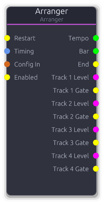
Song arrangement with per-track ControlNorm outputs for enabling/controlling downstream nodes
Song-level arrangement player that outputs per-track level controls synchronized to the graph transport.
Receives an Arrangement via Config In and advances a tick-based playhead. Each arrangement track maps to an unbounded ControlNorm output: the value is the region's level (0.0--1.0) when the playhead is inside a region, otherwise 0.0. Muted, disabled, or non-soloed (when any track is soloed) tracks output 0.0. The Timing input overrides BPM; tempo changes reset the sample accumulator. Enabled gate (disconnected = enabled) forces all outputs to 0.0 when low. Transport seek events resync the tick position. Loop wraps to the start when the arrangement ends. The End gate pulses on loop or completion. Hot-swapping the Config input preserves playhead position and state. Tracks property sets a floor on output count; it also grows to match the arrangement's track count.
Properties
| Name | Type | Default | Range | Help |
|---|
Tracks Playback | Int · Slider | 4 | 1 – 64 | Floor for the number of per-track outputs. Grows automatically to match the arrangement's track count. |
Loop Playback | Bool · Toggle | true | | When enabled, the arrangement wraps to tick 0 on completion and emits an End gate pulse. |
Content BPM Playback | Float · Display | 0 | | BPM from the loaded Arrangement (read-only). Reflects the content's native tempo. |
Inputs
Restart Gate #0 - Rising edge restarts the arrangement from tick 0. Processed even when disabled.
Timing Data(Timing) #1 - Overrides BPM and time signature from the transport. Tempo changes reset the sample accumulator.
Config In Data(Arrangement) #2 - Arrangement data from an Arranger Editor. Hot-swapped each frame: tracks and timing update but playhead is preserved.
Enabled Gate #3 - Gates playback. Disconnected = enabled. When low, all per-track outputs are forced to 0.0 and tick advancement stops.
Outputs
Tempo Control #0 - Effective BPM after Timing port override or transport fallback. Output even when disabled.
Bar Control #1 - Current bar number (0-based) as a raw control value. Derived from current_beat / beats_per_bar.
End Gate #2 - Single-sample gate pulse on arrangement end or loop wrap.
Track Control (Norm) unbounded - Region level (0.0--1.0) when the playhead is inside a region, 0.0 otherwise. Muted/disabled/non-soloed tracks output 0.0.
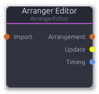
Visual arrangement editor. Click to open arranger panel.
Visual editor for song-level arrangements.
Holds the authoritative Arrangement data (tracks, regions, tempo, time signature) and outputs it via Data port to an Arranger node each frame. The UI sends incremental ArrangerCommand edits (add/remove/move regions, track management, BPM, time signature, loop) through the message bus. In-flight regions (being dragged) are tracked but do not block region output. The Update gate pulses whenever an edit is applied. Timing output carries BPM and time signature. The Import input accepts an external Arrangement for future import support.
Properties
| Name | Type | Default | Range | Help |
|---|
Tempo Timing | Float · Slider | 120 | 20 – 300 | Also settable via SetBpm command. Propagated to the Arrangement and the Timing output. |
Length Timing | Int · Slider | 16 | 1 – 256 | Also settable via SetLengthBars command. Determines the arrangement's total duration. |
Inputs
Import Data(Arrangement) #0 - External Arrangement data for future import support.
Outputs
Arrangement Data(Arrangement) #0 - Full Arrangement data, output every frame. Connect to an Arranger node's Config In.
Update Gate #1 - Single-sample gate pulse after each ArrangerCommand edit is applied.
Timing Data(Timing) #2 - BPM and time signature from the editor's properties. Connect to an Arranger's Timing input.
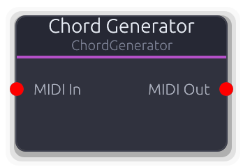
Generates chords from single MIDI notes
Harmonizer that turns single MIDI notes into full chords.
Each incoming note-on becomes the root of a chord built from the selected type (major, minor, seventh, etc.) with configurable voicing and inversions. On note-off, all chord tones for that root are released. Non-note MIDI messages pass through unchanged. Active chords are tracked per root note, so multiple simultaneous roots produce independent chords. Notes are clamped to 0--127 after transposition; inversions raise lower tones by an octave. Open voicing raises inner tones +12; Drop-2 lowers the second-from-top tone by 12. Third inversion only has an effect on seventh chords or larger.
Properties
| Name | Type | Default | Range | Help |
|---|
Chord Type Chord | Enum · Dropdown | 0 | Major / Minor / Diminished / Augmented / Sus2 / Sus4 / Major7 / Minor7 / Dominant7 / Diminished7 / HalfDiminished7 / MinorMajor7 / Augmented7 / Major6 / Minor6 / Major9 / Minor9 / Dominant9 | Interval set used to build the chord. Determines whether the output is a triad, seventh, sixth, or extended chord. |
Voicing Chord | Int · Dropdown | 0 | 0 – 2 | Close keeps all tones within one octave, Open raises inner tones +12, Drop-2 drops the second-from-top tone -12. |
Inversion Chord | Int · Dropdown | 0 | 0 – 3 | Rotates chord tones: each inversion step moves the lowest note up an octave. Third inversion only affects 7th+ chords. |
Inputs
MIDI In MIDI #0 · required - Single-note MIDI input - each note becomes the chord root.
Outputs
MIDI Out MIDI #0 - Multiple simultaneous note-ons per input note. Non-note messages pass through unchanged.
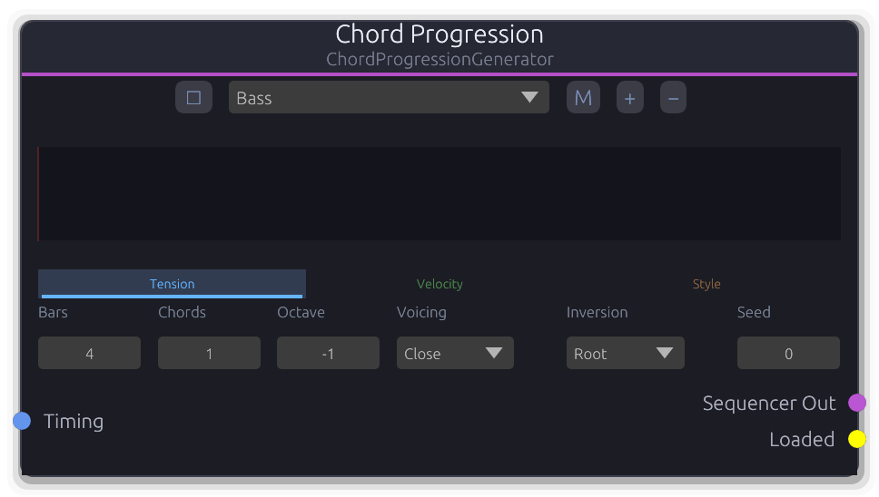
Per-layer curve-driven chord progression generator with polymetric support
Generates chord progressions with per-layer curves for tension, velocity, and style.
Each layer defines its own bar count and chords-per-bar, enabling polymetric progressions. Generation blends user-drawn curves with fBm noise (controlled by the Mix knob) to select chord degree, velocity, and voicing style per chord slot. Generation runs on a background thread -- property changes queue a request (when auto-regen is enabled) and only the latest request is processed. Connect Sequencer Out to a Sequencer Editor to import and edit the result. The Loaded gate pulses once after each completed generation triggered by the Regenerate command. The Timing input overrides BPM and time signature from the transport.
Properties
| Name | Type | Default | Range | Help |
|---|
Key Progression | Int · SpinBox | 60 | 0 – 127 | Root note for the progression. Combined with Scale to define available chord degrees. |
Scale Progression | Enum · Dropdown | 1 | Chromatic / Major / Minor / HarmonicMinor / MelodicMinor / Dorian / Phrygian / Lydian / Mixolydian / Aeolian / Locrian / MajorPentatonic / MinorPentatonic / Blues / WholeTone / Diminished | Musical scale for chord construction. |
Extensions Progression | Enum · Dropdown | 0 | Triads / Sevenths / Extended | Chord complexity: Triads, Sevenths, or Extended (9ths). |
Mix fBm | Float · Knob | 0 | 0 – 1 | At 0.0 chord selection follows curves exclusively; at 1.0 it follows fBm noise exclusively. |
Complexity fBm | Int · Slider | 4 | 1 – 8 | Number of fBm octaves. More layers produce finer harmonic detail at the cost of predictability. |
Persistence fBm | Float · Knob | 0.5 | 0 – 1 | Controls how much weight higher fBm octaves carry. Higher values produce more dissonant or surprising chord choices. |
Rate fBm | Float · Knob | 1 | 0.1 – 10 | Spacing between fBm samples. Lower values produce smoother progressions; higher values jump between distant chords. |
Seed Generation | Int · SpinBox | 0 | 0 – 9999 | Seed for deterministic fBm generation. Same seed + same parameters = same progression. |
Inputs
Timing Data(Timing) #0 - Overrides BPM and time signature from the transport. When disconnected, values come from the graph transport.
Outputs
Sequencer Out Data(Sequence) #0 - Generated MidiSequencer data, streamed every frame. Connect to a Sequencer Editor's Import port to edit.
Loaded Gate #1 - Single-frame gate pulse emitted when a Regenerate command completes (not on auto-regen property changes).
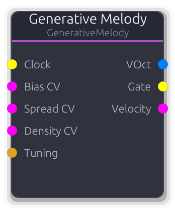
Marbles-style clocked random note/gate generator with scale quantization
Clocked random note and gate generator with scale quantization, inspired by Mutable Instruments Marbles.
Each rising edge on the Clock input generates a new pitch from a bell-curve distribution shaped by Bias (center) and Spread (width), quantized to the selected scale. Gate density controls the probability that a clock step produces a note; gate length sets the duration as a fraction of the measured clock period. Jitter adds random timing offset to gate events. The Lock parameter controls sequence recall: at 0.0 every step is fully random; at 1.0 the cached sequence replays deterministically. Intermediate values probabilistically replace cached steps. The cache size equals the Steps property. Bias, Spread, and Density can be modulated via CV inputs that override the corresponding properties. VOct output is constant across the buffer (updated on each clock step). The Tuning port overrides 12-EDO divisions and applies a V/Oct offset.
Properties
| Name | Type | Default | Range | Help |
|---|
Bias Pitch | Float · Knob | 0.5 | 0 – 1 | Center of the pitch distribution within the octave range. Overridden when Bias CV is connected. |
Spread Pitch | Float · Knob | 0.5 | 0 – 1 | Width of the pitch distribution. At 0.0 every note equals the bias center; at 1.0 the full octave range is used. Overridden when Spread CV is connected. |
Steps Pitch | Int · SpinBox | 8 | 2 – 32 | Number of steps in the lock buffer. The step index wraps at this value. |
Scale Pitch | Enum · Dropdown | 1 | Chromatic / Major / Minor / HarmonicMinor / MelodicMinor / Dorian / Phrygian / Lydian / Mixolydian / Aeolian / Locrian / MajorPentatonic / MinorPentatonic / Blues / WholeTone / Diminished | Musical scale for pitch quantization. |
Root Pitch | Int · SpinBox | 60 | 0 – 127 | Root note (MIDI 0–127). |
Octave Range Pitch | Int · SpinBox | 2 | 1 – 5 | Pitch range in octaves (1–5). |
Lock Memory | Float · Knob | 0 | 0 – 1 | Probability of replaying the cached step. At 0.0 every step is freshly random; at 1.0 the cached sequence loops unchanged. |
Gate Density Rhythm | Float · Knob | 0.5 | 0 – 1 | Probability that each clock step produces a gate. Overridden when Density CV is connected. |
Gate Length Rhythm | Float · Knob | 0.5 | 0.1 – 1 | Gate duration as a fraction of the measured clock period. Gate-off may span into the next buffer. |
Jitter Rhythm | Float · Knob | 0 | 0 – 1 | Random timing offset applied to gate-on events. Maximum displacement is half the clock period. |
Inputs
Clock Gate #0 · required - Each rising edge advances the step index and generates a new pitch/gate/velocity decision. Clock period is measured between edges.
Bias CV Control (Norm) #1 · required - Overrides the Bias property when connected. Clamped to 0.0--1.0.
Spread CV Control (Norm) #2 · required - Overrides the Spread property when connected. Clamped to 0.0--1.0.
Density CV Control (Norm) #3 · required - Overrides the Gate Density property when connected. Clamped to 0.0--1.0.
Tuning Data(Tuning) #4 - Overrides the default 12-EDO divisions-per-octave and applies a V/Oct offset to the pitch output.
Outputs
VOct V/Oct #0 - Scale-quantized V/Oct pitch, constant across the buffer. Updated on each clock step that produces a gate.
Gate Gate #1 - High for the gate-length fraction of the clock period. Previous gate is closed before a new one opens.
Velocity Control (Norm) #2 - Random velocity shaped by Bias (higher bias shifts the distribution upward). Updated per clock step.
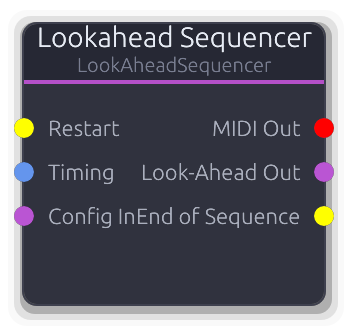
MIDI sequencer with lookahead for visualization and practice features
MIDI sequencer with a lookahead window for score visualization and practice features.
Plays back a MidiSequencer with sample-accurate timing while also computing upcoming notes (1--16 bars ahead) that the UI renders as a grand staff or scrolling notation. The Timing input overrides BPM from the transport. An optional count-in metronome plays before the sequence starts. The lookahead buffer is sent to the UI via poll_response each process cycle. Config In accepts a MidiSequencer from a file loader or sequencer editor; when first loaded the sequence auto-plays. The Restart gate restarts from the beginning; End of Sequence pulses when the sequence finishes.
Properties
| Name | Type | Default | Range | Help |
|---|
Key Signature Notation | Enum · Dropdown | 0 | CMajor / GMajor / DMajor / AMajor / EMajor / BMajor / FSharpMajor / CSharpMajor / FMajor / BFlatMajor / EFlatMajor / AFlatMajor / DFlatMajor / GFlatMajor / CFlatMajor | Determines accidental rendering in the grand staff display. Does not affect MIDI output. |
Look-Ahead Bars Timing | Int · Slider | 4 | 1 – 16 | How many bars of upcoming notes to compute each process cycle for the grand staff display. |
Count-In Bars Timing | Int · Slider | 0 | 0 – 16 | Number of metronome count-in bars before sequence playback begins. 0 = no count-in. |
Staff Offset Staff | Vec2 · XYPad | Vec2(Vec2 { x: 0.0, y: -140.0 }) | | Pixel offset for the grand staff overlay in the UI. Does not affect audio. |
Staff Scale Staff | Vec2 · XYPad | Vec2(Vec2 { x: 400.0, y: 120.0 }) | | Size scaling for the grand staff overlay in the UI. Does not affect audio. |
Inputs
Restart Gate #0 - Rising edge restarts the sequence from tick 0.
Timing Data(Timing) #1 - Overrides BPM and time signature from the transport. When disconnected, values come from the graph transport.
Config In Data(Sequence) #2 - MidiSequencer data from a file loader or sequencer editor. Auto-plays on first load.
Outputs
MIDI Out MIDI #0 - Sample-accurate MIDI events from the current playback position.
Look-Ahead Out Data(Sequence) #1 - Lookahead buffer for grand staff / notation visualization. Also sent via poll_response for the UI.
End of Sequence Gate #2 - Gate pulse emitted when the sequence reaches its end.
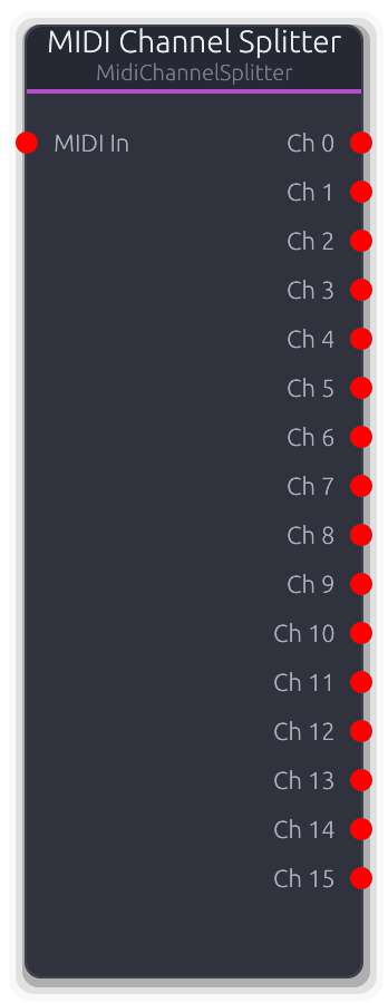
Routes MIDI events by channel to separate outputs. Each output receives events from one MIDI channel.
Demultiplexes a multi-channel MIDI stream into separate per-channel outputs.
Each event is routed to the output matching its MIDI channel (channel 0 to output 0, channel 1 to output 1, etc.). Events on channels beyond the configured output count are silently dropped. The number of outputs is controlled by the Channels property and capped at 16.
Properties
| Name | Type | Default | Range | Help |
|---|
Channels | Int · Slider | 16 | 1 – 16 | How many per-channel outputs to create. Events on channels beyond this count are dropped. |
Inputs
MIDI In MIDI #0 · required - Combined multi-channel MIDI stream to split.
Outputs
Ch MIDI unbounded - Unbounded per-channel MIDI output. Output index matches the MIDI channel number (wire format).
Loads Standard MIDI Files and converts to sequencer configuration. Supports file paths or raw bytes with optional tempo override.
Loads a Standard MIDI File (.mid) and produces a MidiSequencer on its output for downstream playback.
Accepts a MidiSource (file path or raw bytes), a ConstantValue file path, or a full MidiFileLoaderConfig via the Config input. When no Config input is connected, falls back to the embedded source and tempo properties. An optional tempo override rescales all event timestamps proportionally (original_tempo / new_tempo). Parsing only runs when the config changes (detected via a string key including tempo). The Loaded gate pulses once when a file is successfully parsed. Timing Out carries BPM and time signature from the loaded file.
Inputs
Config In Data(Unknown) #0 - Accepts MidiSource, ConstantValue::FilePath, or full MidiFileLoaderConfig. Overrides the embedded source property when connected.
Outputs
Sequencer Out Data(Sequence) #0 - Cached MidiSequencer data, streamed every frame. Connect to a Sequencer or Sequencer Editor.
Loaded Gate #1 - Single-frame gate pulse emitted when a file is successfully parsed (including on initial embedded load).
Timing Data(Timing) #2 - BPM and time signature from the loaded MIDI file. Defaults to 4/4 if not specified in the file.
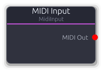
Receives MIDI events from a virtual MIDI device
Receives live MIDI from a hardware controller or virtual port via the MIDI Device Manager pub/sub system.
Set the Device property to a VirtualDeviceId to subscribe; the audio thread establishes the subscription and injects a crossbeam receiver. Events are drained from the receiver each process cycle. System messages (clock, start, etc.) always pass through; channel messages are filtered by the Channel property (0 = all). When Device is 0 (none) the node produces no output. Changing the Device property clears stale subscriptions immediately.
Properties
| Name | Type | Default | Range | Help |
|---|
Device | Int | 0 | 0 – 65535 | VirtualDeviceId to subscribe to. Setting this clears existing subscriptions; the audio thread re-subscribes on the next cycle. |
Channel | Int | 0 | 0 – 16 | Filters channel messages. System messages bypass this filter entirely. |
Outputs
MIDI Out MIDI #0 - MIDI events drained from the subscription receiver each process cycle. Empty when no device is subscribed.
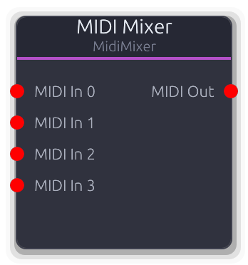
Merges multiple MIDI input streams into a single output stream.
Merges multiple MIDI streams into a single time-ordered output.
All events from all connected inputs are collected, sorted by sample offset, and written to a single output buffer. The number of input ports is controlled by the Inputs property and also grows dynamically via topology overrides as cables are connected.
Properties
| Name | Type | Default | Range | Help |
|---|
Inputs | Int · Slider | 4 | 1 – 64 | Controls the number of visible input ports. Topology overrides may add more as cables are connected. |
Inputs
MIDI In MIDI unbounded - Unbounded MIDI input. Each connected port contributes events to the merged output.
Outputs
MIDI Out MIDI #0 - All input events merged and sorted by sample offset.
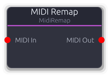
Remaps MIDI channel, transposes notes, scales velocity, and filters note range
MIDI transformer that remaps channels, transposes notes, scales velocity, and filters by note range.
Processing order: source channel filter, then transpose, then note range filter, then velocity scale, then target channel remap. Events that fail the source channel or note range filters are silently dropped (not passed through). Transpose is applied to NoteOn, NoteOff, and polyphonic Aftertouch messages. Velocity scaling clamps to 1--127 (never produces velocity 0). Non-note messages (CC, pitch bend, etc.) pass through with only channel remapping applied.
Properties
| Name | Type | Default | Range | Help |
|---|
Source Ch | Int | 0 | 0 – 16 | Events on non-matching channels are dropped entirely (not passed through). |
Target Ch | Int | 0 | 0 – 16 | Rewrites the channel on all output events. 0 = keep the original channel. |
Transpose | Int | 0 | -48 – 48 | Semitone offset applied to NoteOn, NoteOff, and polyphonic Aftertouch. Result clamped to 0--127. |
Note Min | Int | 0 | 0 – 127 | Notes below this value are dropped (checked after transpose). |
Note Max | Int | 127 | 0 – 127 | Notes above this value are dropped (checked after transpose). |
Vel Scale | Int | 100 | 0 – 200 | Velocity multiplier as a percentage. Output velocity is clamped to 1--127 (never produces velocity 0 NoteOn). |
Inputs
MIDI In MIDI #0 · required - Incoming MIDI events to remap.
Outputs
MIDI Out MIDI #0 - Remapped MIDI events (transposed, channel-shifted, velocity-scaled).
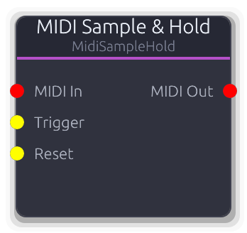
Latch polyphonic MIDI note state on gate trigger
Latches polyphonic MIDI note state on each gate trigger.
In Trigger mode, incoming MIDI notes are tracked silently via MidiNoteTracker. On each Trigger rising edge, the tracker diffs the current input state against the held output state and emits the minimal note-off/note-on set to transition cleanly. Between triggers the output holds the captured snapshot -- stuck notes are impossible because the tracker manages all diffing. The Reset input flushes all held notes (all note-offs). In Pass mode, events pass through transparently (bypass). Disconnecting the MIDI input flushes the tracker silently. Max Notes limits the snapshot size; oldest notes are dropped when full.
Properties
| Name | Type | Default | Range | Help |
|---|
Max Notes | Int · SpinBox | 8 | 1 – 16 | Maximum number of notes in the held snapshot. When full, the oldest note is dropped to make room. |
Mode | Enum · Dropdown | 0 | Trigger / Pass | Trigger: tracks silently, captures on gate edge. Pass: all events pass through (bypass). |
Inputs
MIDI In MIDI #0 · required - Source MIDI stream. In Trigger mode notes are tracked silently until capture. In Pass mode events flow straight through.
Trigger Gate #1 · required - Rising edge captures the current input note state and emits the diff to the output.
Reset Gate #2 · required - Rising edge flushes all held notes (emits note-offs for everything in the snapshot).
Outputs
MIDI Out MIDI #0 - In Trigger mode: the minimal diff events (note-offs then note-ons) on each capture. In Pass mode: all input events.
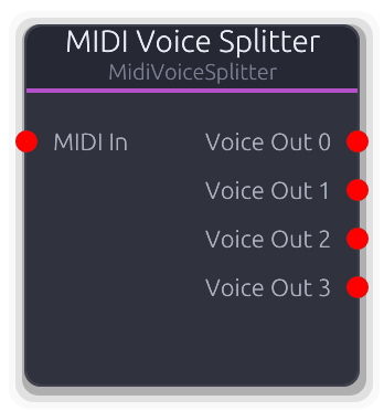
Splits polyphonic MIDI into monophonic voices. Voice count determined by connected outputs.
Splits polyphonic MIDI into separate monophonic voice outputs with oldest-note voice stealing.
Each NoteOn is assigned to the first idle output; when all outputs are busy, the oldest voice is stolen (NoteOff sent before the new NoteOn). NoteOff is routed to whichever output holds that note. Non-note messages (CC, pitch bend, etc.) are broadcast to all outputs. All output events are on channel 1 regardless of the input channel. The Voices property controls the number of outputs.
Properties
| Name | Type | Default | Range | Help |
|---|
Voices | Int · Slider | 4 | 1 – 64 | Controls the number of monophonic output ports. Determines maximum polyphony. |
Inputs
MIDI In MIDI #0 · required - Polyphonic MIDI input to split across voices.
Outputs
Voice Out MIDI unbounded - Each output carries one monophonic voice on channel 1. Non-note messages are broadcast to all outputs.
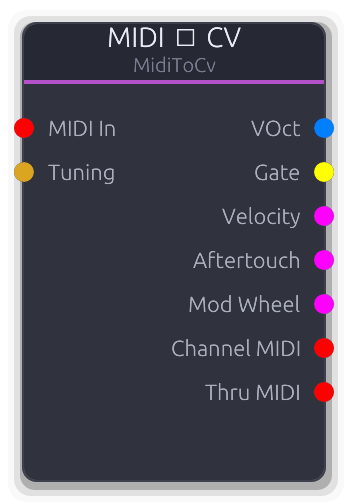
Converts MIDI notes to VOct pitch CV and gate signals
Converts MIDI note events into modular-style CV signals for driving oscillators, envelopes, and modulation sources.
Outputs volt-per-octave pitch, a gate, normalized velocity, channel/poly aftertouch, and mod wheel (CC 1). In Last mode every note passes through (classic mono last-note priority with note stack -- releasing a note restores the previous pitch). In Exclusive mode the node claims one note at a time and strips it from the Thru output; chain several Exclusive nodes for manual polyphonic voice allocation. The Channel MIDI output always carries all channel-matched events regardless of voice mode. Non-note events (CC, aftertouch) are never claimed in Exclusive mode and always appear on Thru. When the Tuning port is connected it overrides divisions-per-octave and applies a V/Oct offset to the pitch output.
Properties
| Name | Type | Default | Range | Help |
|---|
Voice Mode Voice | Enum · Dropdown | 0 | Last / Exclusive | Last: responds to every note, outputs the most recent pitch, all events forwarded to Thru. Exclusive: claims one note while idle, passes new notes to Thru for downstream voices. |
Reference Note | Int · SpinBox | 60 | 0 – 127 | MIDI note that maps to 0V. Pitch = (note - reference) / divisions_per_octave. |
Channel | Int · SpinBox | 0 | 0 – 16 | Events on non-matching channels bypass all processing and go straight to Thru. |
Inputs
MIDI In MIDI #0 · required - MIDI events to convert. Only note, aftertouch, and CC 1 messages are extracted; other events pass through.
Tuning Data(Tuning) #1 - Overrides the default 12-EDO divisions-per-octave and applies a V/Oct offset to the pitch output.
Outputs
VOct V/Oct #0 - Volt-per-octave pitch. Constant across the buffer, updated on each note-on. 0V at the reference note.
Gate Gate #1 - High while any note is held. In Last mode, stays high across note transitions; falls low only when the note stack empties.
Velocity Control (Norm) #2 - Most recent note-on velocity, normalized 0.0--1.0. Resets to 0 when all notes release.
Aftertouch Control (Norm) #3 - Channel or polyphonic aftertouch pressure, normalized 0.0--1.0. Both aftertouch types write to this output.
Mod Wheel Control (Norm) #4 - Mod wheel (CC 1) as normalized 0.0--1.0.
Channel MIDI MIDI #5 - All channel-matched MIDI events, forwarded regardless of voice mode or claim status.
Thru MIDI MIDI #6 - In Last mode: all channel-matched events. In Exclusive mode: only unclaimed events. Non-matching channels always pass through.
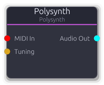
Polyphonic MIDI synthesizer with configurable waveform and envelope
Self-contained polyphonic synthesizer that receives MIDI and outputs stereo audio directly.
Up to 8 simultaneous voices, each with its own oscillator and ADSR envelope. Voice allocation prefers idle voices; when all are busy the oldest active voice is stolen with velocity smoothing and a cosine fade-in to prevent clicks. NoteOff is reference-counted: if the same note is triggered multiple times it only releases when all matching note-offs arrive. Output is the sum of all voices divided by max_voices, then scaled by Master Gain. Disconnecting the MIDI input releases all active voices. The Tuning port overrides 12-EDO divisions and applies a V/Oct offset.
Properties
| Name | Type | Default | Range | Help |
|---|
Waveform | Enum · Dropdown | 0 | Sine / Square / Sawtooth / Triangle | Oscillator waveform: Sine, Square, Sawtooth, or Triangle. |
Shape | Envelope · EnvelopeEditor | Envelope(EnvelopeCurve { curve: Curve { keyframes: [Keyframe { time: 0.0, value: 0.0, in_tangent: 0.0, out_tangent: 0.0 }, Keyframe { time: 0.01, value: 1.0, in_tangent: 0.0, out_tangent: 0.0 }, Keyframe { time: 0.11, value: 0.7, in_tangent: 0.0, out_tangent: 0.0 }, Keyframe { time: 0.31, value: 0.0, in_tangent: 0.0, out_tangent: 0.0 }], range: Normalized }, hold_index: Some(2), phase: Idle, time: 0.0, bridge: None }) | | ADSR envelope curve applied to each voice. Reshapes active voices without resetting their phase. |
Inputs
MIDI In MIDI #0 - NoteOn triggers a voice; NoteOn with velocity 0 acts as NoteOff. Disconnecting releases all voices.
Tuning Data(Tuning) #1 - Overrides the default 12-EDO divisions-per-octave and applies a frequency offset to all voices.
Outputs
Audio Out Audio #0 - Sum of all voices divided by max_voices, scaled by Master Gain, as mono-to-stereo.
Polyphonic MIDI synthesizer with configurable waveform and envelope
Polyphonic synthesizer with up to 16 voices and smooth frequency crossfades on voice steal.
Same voice allocation strategy as Polysynth (idle-first, then oldest-note steal) but adds a 16-sample linear crossfade when stealing to smooth frequency discontinuities. Voices are re-initialized at the audio thread's actual sample rate in setup(). NoteOff is reference-counted. Output is the sum of all voices divided by voice count, then scaled by Master Gain. Disconnecting the MIDI input releases all active voices. The Tuning port overrides 12-EDO divisions and applies a frequency offset at note-on time.
Properties
| Name | Type | Default | Range | Help |
|---|
Waveform | Enum · Dropdown | 0 | Sine / Square / Sawtooth / Triangle | Oscillator waveform: Sine, Square, Sawtooth, or Triangle. |
Shape | Envelope · EnvelopeEditor | Envelope(EnvelopeCurve { curve: Curve { keyframes: [Keyframe { time: 0.0, value: 0.0, in_tangent: 0.0, out_tangent: 0.0 }, Keyframe { time: 0.01, value: 1.0, in_tangent: 0.0, out_tangent: 0.0 }, Keyframe { time: 0.11, value: 0.7, in_tangent: 0.0, out_tangent: 0.0 }, Keyframe { time: 0.31, value: 0.0, in_tangent: 0.0, out_tangent: 0.0 }], range: Normalized }, hold_index: Some(2), phase: Idle, time: 0.0, bridge: None }) | | ADSR envelope curve applied to each voice. Reshapes active voices without resetting their phase. |
Inputs
MIDI In MIDI #0 - NoteOn triggers a voice; NoteOn with velocity 0 acts as NoteOff. Disconnecting releases all voices.
Tuning Data(Tuning) #1 - Overrides the default 12-EDO divisions-per-octave and applies a frequency offset at note-on time.
Outputs
Audio Out Audio #0 - Sum of all voices divided by voice count, scaled by Master Gain, as mono-to-stereo.
Quantizes MIDI notes to a musical scale
Snaps MIDI note pitches to the nearest degree in a selected musical scale.
NoteOn pitches are quantized and the original-to-quantized mapping is cached for the corresponding NoteOff, so note-offs always match their note-ons. Changing the Scale or Root Note property flushes all active notes (sends note-offs on channel 1 at sample offset 0) before clearing the mapping cache. Non-note messages pass through unchanged. Snap mode determines the quantization direction: Nearest picks the closest scale degree, Up always rounds up, Down always rounds down. The mapping cache avoids recomputing scale lookups for repeated pitches.
Properties
| Name | Type | Default | Range | Help |
|---|
Scale Scale | Enum · Dropdown | 1 | Chromatic / Major / Minor / HarmonicMinor / MelodicMinor / Dorian / Phrygian / Lydian / Mixolydian / Aeolian / Locrian / MajorPentatonic / MinorPentatonic / Blues / WholeTone / Diminished | Changing the scale flushes all active notes and clears the quantization cache. |
Root Note Scale | Enum · Dropdown | 60 | C-1 / C#-1 / D-1 / D#-1 / E-1 / F-1 / F#-1 / G-1 / G#-1 / A-1 / A#-1 / B-1 / C0 / C#0 / D0 / D#0 / E0 / F0 / F#0 / G0 / G#0 / A0 / A#0 / B0 / C1 / C#1 / D1 / D#1 / E1 / F1 / F#1 / G1 / G#1 / A1 / A#1 / B1 / C2 / C#2 / D2 / D#2 / E2 / F2 / F#2 / G2 / G#2 / A2 / A#2 / B2 / C3 / C#3 / D3 / D#3 / E3 / F3 / F#3 / G3 / G#3 / A3 / A#3 / B3 / C4 / C#4 / D4 / D#4 / E4 / F4 / F#4 / G4 / G#4 / A4 / A#4 / B4 / C5 / C#5 / D5 / D#5 / E5 / F5 / F#5 / G5 / G#5 / A5 / A#5 / B5 / C6 / C#6 / D6 / D#6 / E6 / F6 / F#6 / G6 / G#6 / A6 / A#6 / B6 / C7 / C#7 / D7 / D#7 / E7 / F7 / F#7 / G7 / G#7 / A7 / A#7 / B7 / C8 / C#8 / D8 / D#8 / E8 / F8 / F#8 / G8 / G#8 / A8 / A#8 / B8 / C9 / C#9 / D9 / D#9 / E9 / F9 / F#9 / G9 | The note the scale intervals are built from. Changing this flushes active notes and clears the cache. |
Snap Mode Quantization | Int · Dropdown | 0 | 0 – 2 | Nearest: closest scale degree. Up: next scale degree at or above. Down: next scale degree at or below. |
Inputs
MIDI In MIDI #0 · required - Incoming MIDI. Only NoteOn/NoteOff pitches are altered; all other messages pass through.
Outputs
MIDI Out MIDI #0 - MIDI events with note pitches snapped to the scale. NoteOff pitches match their corresponding quantized NoteOn.
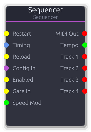
MIDI sequencer that outputs timed MIDI events. Uses graph transport for tempo and play state.
MIDI playback engine synchronized to the graph transport.
Receives a MidiSequencer via Config In and plays back timed MIDI events. The merged MIDI Out carries events with their original channel assignments; per-track outputs (unbounded) carry the same events remapped to channel 1. Tempo comes from the Timing input when connected, otherwise from the graph transport; tempo changes flush stuck notes. The Enabled gate (disconnected = enabled) gates playback and flushes notes on transitions. Restart resets the playhead; Reload hot-swaps the config without resetting position. When Reload is not connected, Config In is polled continuously. Transport seek events cause an immediate seek-and-flush. Loop wraps playback to the loop region when enabled; if loop_end is at the default it auto-extends to cover the entire sequence. The Tracks property sets a floor on output count -- it also grows to match the loaded sequence's track count.
Properties
| Name | Type | Default | Range | Help |
|---|
Tracks Playback | Int · Slider | 4 | 1 – 64 | Floor for the number of per-track outputs. Grows automatically to match the loaded sequence's track count. |
Loop Playback | Bool · Toggle | false | | Wraps playback to the loop region. If loop_end is at the default (960 ticks) it auto-extends to cover the entire sequence. |
Content BPM Playback | Float · Display | 0 | | BPM from the loaded MidiSequencer (read-only). Reflects the content's native tempo. |
Gating Playback | Enum · Dropdown | 0 | None / OneShot / Loop | Gating mode. `None` (default) follows graph transport. `OneShot` plays the pattern once on each `Gate In` rising edge. `Loop` loops while the gate is high. Switching modes flushes any sounding notes. |
Inputs
Restart Gate #0 - Rising edge restarts the sequence from tick 0, flushing all active notes.
Timing Data(Timing) #1 - Overrides BPM and time signature from the transport. Tempo changes flush stuck notes.
Reload Gate #2 - Rising edge hot-swaps the Config In data without resetting the playhead. When disconnected, Config In is polled continuously.
Config In Data(Sequence) #3 - MidiSequencer data from a file loader or sequencer editor. Loaded continuously unless Reload is connected.
Enabled Gate #4 - Gates playback. Disconnected = enabled. Transitions flush all active notes.
Gate In Gate #5 - Clip-launcher gate. In `OneShot` / `Loop` modes, a rising edge resets the local playhead to 0 and starts playback. `Loop` stops on falling edge; `OneShot` plays through. Ignored in `None` mode.
Speed Mod Control #6 - Multiplier on playback rate. `1.0` = normal, `0.5` = half speed, `2.0` = double, `0.0` = freeze playhead (resumable from the same tick when the value comes back up). Negative values clamp to zero. Disconnected = `1.0` (no effect). Works in all gating modes.
Outputs
MIDI Out MIDI #0 - Merged MIDI from all tracks with original channel assignments preserved.
Tempo Control #1 - Effective BPM after Timing port override or transport fallback. Useful for downstream tempo-dependent effects.
Track MIDI unbounded - Per-track MIDI output with all events remapped to channel 1. One output per sequencer track.
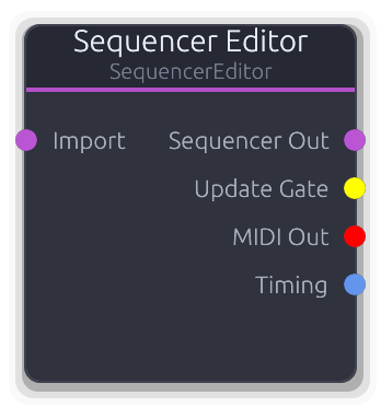
Visual MIDI sequencer editor with piano roll interface. Click to open editor panel.
Visual MIDI sequencer editor with a piano-roll interface.
Holds the authoritative MidiSequencer state and outputs it via Data port to a Sequencer node each frame. The UI sends incremental SequencerCommand edits (add, move, resize, delete notes; track mute/solo/channel changes; BPM and time signature updates). The node maintains a note_map as the single source of truth and rebuilds track MIDI events from it. In-flight notes (being dragged) are excluded from events until they land. The Import input accepts a MidiSequencer from an external source (file loader, chord progression); use the ImportFromInput command to merge it. Audition MIDI (note preview during editing) is output on the MIDI Out port on the configured audition channel. The Update Gate pulses whenever an edit is applied. Timing output carries BPM and time signature from the editor's properties.
Properties
| Name | Type | Default | Range | Help |
|---|
Audition Channel | Int · Slider | 1 | 0 – 15 | MIDI channel for note preview when clicking notes in the editor. Uses display numbering (0--15). |
Inputs
Import Data(Sequence) #0 - External MidiSequencer to import. Connected data is cached; use the ImportFromInput command to merge it into the editor.
Outputs
Sequencer Out Data(Sequence) #0 - Full MidiSequencer data, output every frame. Connect to a Sequencer node's Config In.
Update Gate Gate #1 - Single-frame gate pulse after each SequencerCommand edit is applied.
MIDI Out MIDI #2 - Note audition/preview events on the configured audition channel. Triggered by SequencerAudition commands.
Timing Data(Timing) #3 - BPM, time signature, and key signature from the editor's properties. Connect to a Sequencer's Timing input.
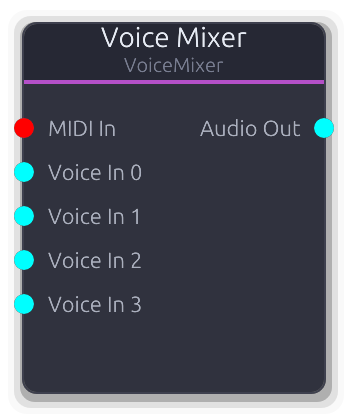
MIDI-controlled polyphonic mixer with per-voice ADSR envelopes and voice stealing
MIDI-controlled polyphonic voice mixer with per-voice ADSR envelopes and voice stealing.
Allocates MIDI notes to voice slots (idle-first, then oldest-note steal). Each slot gates one unbounded audio input with an independent ADSR envelope, velocity smoothing, and cosine fade-in. All gated voices are summed, divided by the connected voice count (fixed denominator -- not the number of active voices), then scaled by Master Gain. NoteOff is reference-counted. The slot pool resizes dynamically to match the number of connected audio inputs. Disconnecting the MIDI input releases all active slots.
Properties
| Name | Type | Default | Range | Help |
|---|
Voices | Int · Slider | 4 | 1 – 64 | Controls the number of visible audio input ports (after the MIDI port). |
Shape | Envelope · EnvelopeEditor | Envelope(EnvelopeCurve { curve: Curve { keyframes: [Keyframe { time: 0.0, value: 0.0, in_tangent: 0.0, out_tangent: 0.0 }, Keyframe { time: 0.005, value: 1.0, in_tangent: 0.0, out_tangent: 0.0 }, Keyframe { time: 0.105000004, value: 0.8, in_tangent: 0.0, out_tangent: 0.0 }, Keyframe { time: 0.305, value: 0.0, in_tangent: 0.0, out_tangent: 0.0 }], range: Normalized }, hold_index: Some(2), phase: Idle, time: 0.0, bridge: None }) | | ADSR envelope applied to each voice slot. Reshapes active slots without resetting their phase. |
Master Gain | Float · Knob | 1 | 0 – 4 | Multiplier applied after sum / voice_count. Gain normalization uses the total voice count, not the active count. |
Inputs
MIDI In MIDI #0 · required - MIDI notes for voice allocation. Disconnecting releases all active slots.
Voice In Audio unbounded - Audio from a voice processing chain. Slot index maps directly to input index (after the MIDI port). Unconnected slots contribute silence.
Outputs
Audio Out Audio #0 - Sum of all gated voices divided by voice count, scaled by Master Gain.
Source
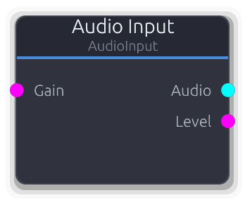
Hardware audio capture (microphone, line in)
Captures live audio from a hardware input device (microphone, line in, audio interface) and injects it into the graph.
Device names come from the OS audio subsystem. "Default" uses the system default input. Streams open at stereo regardless of the device's native channel count; multi-channel interfaces route through the OS stereo bus.
Gain uses exponential scaling above unity: 0.0 = silent, 0.5 = unity, 1.0 = +12 dB. Defaults to unity (0.5) when the Gain input is disconnected.
The internal ring buffer holds ~100 ms at 48 kHz. If the graph cannot keep up, the oldest input samples are dropped. This node does not record -- use Audio Looper or Sample Recorder downstream for capture.
Properties
| Name | Type | Default | Range | Help |
|---|
Device | StringList · Dropdown | "Default" | | Which hardware input device to capture from. "Default" uses the OS default. Selecting a device clears the active stream so the engine re-subscribes on the next process cycle. |
Refresh Devices | Bool · Toggle | false | | Re-scan available audio input devices. Runs on a background thread; no-op if an enumeration is already in flight. |
Channels | Enum · Dropdown | 1 | Mono / Stereo | Mono duplicates channel 0 to both L/R -- use with single-mic setups plus a Stereo Panner downstream. Stereo uses channels 0+1 as a stereo pair. |
Inputs
Gain Control (Norm) #0 - Input gain control. Exponential above unity: 0.0 = silent, 0.5 = unity, 1.0 = +12 dB. Defaults to unity when disconnected.
Outputs
Audio Audio #0 - Captured stereo audio from the selected hardware device. Outputs silence when no consumer is attached or the ring buffer is empty.
Level Control (Norm) #1 - RMS level of the captured signal as ControlNorm, suitable for metering without an Envelope Follower. Smoothed to avoid jitter (only updates when the change exceeds 0.001).
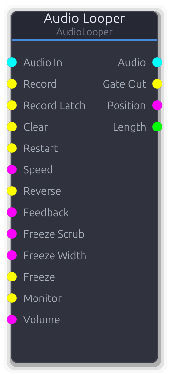
Gate-triggered audio loop recorder with overdub
Gate-triggered loop recorder with multi-layer overdub. Hold Record to capture; the first recording defines the loop length and all subsequent overdubs wrap within it.
Two recording inputs: Record (hold to record, release to stop) and Record Latch (rising edge toggles record on/off for hands-free or foot pedal use). When Record Latch is connected, it overrides the Record gate.
With Layers set to 1, overdubs mix directly into the base buffer. Feedback is applied during playback (not just overdub): at 1.0 the loop plays forever, below 1.0 the buffer decays each pass like a delay line. With Layers > 1, each overdub is stored on a separate layer; Clear removes the most recent layer (undo), and Feedback is ignored to preserve undo integrity.
Freeze holds the current position, sustaining audio as a crossfaded micro-loop around the freeze point. Freeze Scrub picks where in the loop you are frozen (ignored without Freeze). Freeze Width sets the size of the micro-loop window.
Speed uses exponential scaling (0.25x-4x). Reverse plays the loop backwards. Quantize defers record start/stop to the next beat boundary using transport position. Monitor passes input audio through to the output during recording to prevent latency surprise. Max Duration pre-allocates the buffer and cannot be changed while a loop is loaded.
Properties
| Name | Type | Default | Range | Help |
|---|
Max Duration | Float · Knob | 30 | 1 – 120 | Pre-allocates the recording buffer. Cannot be changed while a loop is loaded. |
Monitor | Bool · Toggle | true | | Pass input audio through to output during recording and overdub. Prevents the latency surprise of hearing silence while playing. The Monitor gate input overrides this property when connected. |
Quantize | Bool · Toggle | false | | Defer record start/stop to the next beat boundary using transport position. Useful for keeping loops in sync with a tempo. |
Fade | Float · Knob | 5 | 0 – 50 | Crossfade length at loop boundaries. Applied as an equal-power fade at the wrap point to prevent clicks. Also used as the crossfade duration when entering/exiting freeze mode. |
Layers | Int · Knob | 1 | 1 – 32 | Maximum number of overdub layers. At 1, overdubs mix into the base buffer and Feedback controls decay. Above 1, each overdub is stored separately; Clear removes the most recent layer (undo). When the layer limit is reached, the oldest non-base layer is merged down into the base. |
Inputs
Audio In Audio #0 · required - Stereo audio signal to record into the loop. During playback without recording, this input is ignored unless Monitor is on.
Record Gate #1 - Hold high to record/overdub, release to stop. The first recording pass defines the loop length; subsequent holds overdub within it. Ignored when Record Latch is connected.
Record Latch Gate #2 - Rising edge toggles record on/off (hands-free / foot pedal). Overrides the Record gate when connected.
Clear Gate #3 - Rising edge erases content. With Layers > 1, clears the most recent layer (undo). With 1 layer remaining, performs a full reset (erases buffer, stops playback, resets latch state).
Restart Gate #4 - Rising edge resets playback position to the loop start.
Speed Control (Norm) #5 - Playback speed with exponential scaling: 0.0 = 0.25x, 0.5 = normal, 1.0 = 4x. Defaults to normal speed when disconnected.
Reverse Gate #6 - Gate high reverses the playback direction. Resets to forward when disconnected.
Feedback Control (Norm) #7 - Loop buffer decay amount (Layers = 1 only). Applied during playback, not just overdub: at 1.0 (default when disconnected) the loop plays forever; below 1.0, the buffer decays each pass like a delay line. Ignored in multi-layer mode to preserve undo integrity.
Freeze Scrub Control (Norm) #8 - Picks where in the loop you are frozen (0.0 = start, 1.0 = end). Only active while Freeze is held; ignored otherwise. Smoothed to avoid clicks on abrupt CV changes.
Freeze Width Control (Norm) #9 - Size of the frozen micro-loop window as a fraction of the loop length. Defaults to ~1% (~20 ms at typical loop lengths) when disconnected. Smoothed to prevent clicks.
Freeze Gate #10 - Gate high freezes playback at the current position. Audio sustains as a crossfaded micro-loop around the freeze point. Resets to normal playback when disconnected.
Monitor Gate #11 - Gate to toggle input monitoring on/off. Overrides the Monitor property when connected. Falls back to the property value when disconnected.
Volume Control (Norm) #12 - Output volume scaling. Defaults to 1.0 (full) when disconnected.
Outputs
Audio Audio #0 - Stereo mix of all recorded layers (interpolated). Includes the monitored input signal during overdub if Monitor is on.
Gate Out Gate #1 - High while the loop is playing back (after the first recording completes). Goes low when cleared.
Position Control (Norm) #2 - Normalized playback position within the loop (0.0-1.0).
Length Control #3 - Loop length in beats (derived from sample count and transport BPM). Zero when no loop is loaded or BPM is zero.
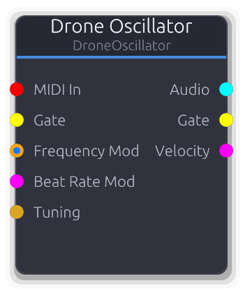
Detuned beating sines for ambient drone textures
Layers multiple tightly-detuned sine waves to produce slow beating and interference patterns - the foundation for ambient pads and drones.
Voices are spread symmetrically around the center frequency with sub-Hz offsets determined by the Beat Rate. For N voices, offsets range from `-beat_rate/2` to `+beat_rate/2` Hz. Warmth blends in a second harmonic (one octave up) at half amplitude per voice. Beat Rate CV maps 0.0-1.0 linearly to 0.01-5.0 Hz and overrides the property. The output is normalized by voice count.
Properties
| Name | Type | Default | Range | Help |
|---|
Frequency Drone | Float (Hz) · LogSlider | 440 | 20 – 2000 | Center pitch around which all voices are detuned. |
Voices Drone | Int · Slider | 4 | 2 – 8 | Number of detuned sine voices (2–8). |
Beat Rate Drone | Float (Hz) · Slider | 0.5 | 0.01 – 5 | Total frequency spread across all voices in Hz. Higher values produce faster beating. |
Warmth Drone | Float · Knob | 0 | 0 – 1 | Blends a second harmonic (octave up) into each voice at half amplitude for a rounder tone. |
Phase Reset Drone | Bool · Checkbox | false | | Reset phase to zero on gate/MIDI retrigger. Off by default - free-running phase lets the amp envelope shape the attack naturally. |
Inputs
MIDI In MIDI #0 - MIDI note data. Sets center pitch, resets all voice phases on note-on, and drives Gate/Velocity outputs.
Gate Gate #1 - Rising edge resets all voice phases. Shares trigger state with MIDI gate.
Frequency Mod Control (Freq) | V/Oct #2 - Pitch input. VOct offsets MIDI or the Frequency knob exponentially; ControlFreq overrides the knob in Hz.
Beat Rate Mod Control (Norm) #3 - Overrides the Beat Rate property. 0.0 maps to 0.01 Hz, 1.0 maps to 5.0 Hz (linear).
Tuning Data(Tuning) #4 - Tuning configuration - overrides local divisions/octave.
Outputs
Audio Audio #0 - Summed drone voices, normalized by voice count.
Gate Gate #1 - Forwards gate events from MIDI input. Silent when MIDI is disconnected.
Velocity Control (Norm) #2 - Last MIDI note velocity as 0.0-1.0. Only emits when MIDI is connected.
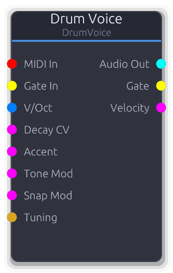
All-in-one percussion synthesizer with multiple drum modes
All-in-one percussion synthesizer with selectable drum modes. Each mode uses a different internal topology of oscillators, noise, filters, and envelopes tuned for that drum sound.
Triggering: a rising edge on the Gate input or a MIDI NoteOn resets all envelopes, oscillator phases, and filter state. Both trigger sources are additive - either one fires the drum. The voice auto-deactivates when its amplitude envelope completes, zeroing the remaining output buffer for efficiency.
Pitch is the sum of the Pitch property, MIDI note offset (note - 60 in octaves), and the V/Oct input. The combined value maps to a frequency multiplier via 2^pitch, so +1 = one octave up, -1 = one octave down. Decay CV, Tone Mod, and Snap Mod each replace their respective property value when connected (not additive). Drive applies tanh soft clipping with gain ranging from 1x to 9x.
Mode-specific topologies: Kick uses a sine oscillator with pitch sweep plus noise click. Snare combines a sine body with bandpass-filtered noise. Hihat runs white noise through highpass and bandpass filters. Tom is similar to kick but higher pitch and less sweep. Clap fires three rapid bandpass-filtered noise bursts. Rimshot blends two detuned sine oscillators with a noise transient. Cowbell uses two detuned clipped-sine oscillators through a bandpass filter.
Properties
| Name | Type | Default | Range | Help |
|---|
Mode Drum | Enum · Dropdown | 0 | Kick / Snare / Hihat / Tom / Clap / Rimshot / Cowbell | Selects the synthesis topology. Each mode has a different combination of oscillators, noise, and filters, so changing the mode fundamentally changes the sound character. |
Pitch Drum | Float · Slider | 0 | -1 – 1 | Base pitch offset from the mode's default frequencies. Combined additively with MIDI note offset and V/Oct input before converting to a frequency multiplier via 2^pitch. |
Decay Drum | Float · Slider | 0.5 | 0 – 1 | How long the sound rings out. Interpolates between the mode's minimum and maximum decay times. Each mode defines its own range (e.g. kick 50-800 ms, hihat 10-400 ms). |
Tone Drum | Float · Slider | 0.5 | 0 – 1 | Tonal character, with mode-specific behavior. For kick, it controls pitch sweep speed. For snare/clap/cowbell, it controls filter cutoff. For hihat, it controls filter resonance. Higher values generally produce brighter sounds. |
Snap Drum | Float · Slider | 0.3 | 0 – 1 | Noise transient at the attack, with mode-specific behavior. For kick/tom, it controls a white noise click at the start. For snare, it crossfades between body oscillator and filtered noise. For clap, it scales overall noise level. For rimshot, it blends noise into the tonal mix. |
Drive Drum | Float · Slider | 0 | 0 – 1 | Soft-clipping distortion applied after the Accent scaling. Uses tanh saturation with a gain ranging from 1x (clean) to 9x (heavy). Below 0.001, drive is bypassed entirely. |
Inputs
MIDI In MIDI #0 - MIDI note input. NoteOn triggers the drum and sets a pitch offset based on the note number (C4/note 60 = zero offset). Gate and velocity events are forwarded to the output ports.
Gate In Gate #1 · required - Rising edge triggers the drum hit. Only rising edges trigger; falling edges are ignored. Can fire alongside MIDI - both sources are independent triggers.
V/Oct V/Oct #2 - Pitch offset in volts-per-octave, added to the Pitch property and any MIDI note offset. When disconnected, contributes zero offset.
Decay CV Control (Norm) #3 - Replaces the Decay property value when connected. The CV value is used directly as the 0-1 decay parameter. When disconnected, the property value is used.
Accent Control (Norm) #4 - Scales the output amplitude before drive processing. Typically driven by a sequencer velocity output. Defaults to 1.0 when disconnected.
Tone Mod Control (Norm) #5 - Replaces the Tone property value when connected. The CV value is used directly. When disconnected, the property value is used.
Snap Mod Control (Norm) #6 - Replaces the Snap property value when connected. The CV value is used directly. When disconnected, the property value is used.
Tuning Data(Tuning) #7 - Tuning configuration for MIDI pitch quantization. Overrides the default 12-TET divisions per octave and V/Oct offset.
Outputs
Audio Out Audio #0 - Mono drum audio (emitted as identical L/R). Includes accent scaling and drive processing. Silent when the voice is inactive.
Gate Gate #1 - Gate events forwarded from the MIDI input. Not emitted when triggered by the Gate input port alone.
Velocity Control (Norm) #2 - MIDI velocity forwarded as normalized CV. Only emitted when MIDI input is connected.
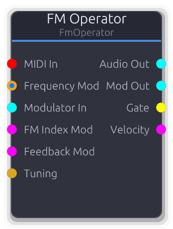
Frequency modulation synthesis operator with external modulation and feedback
Single FM synthesis operator that works as both carrier and modulator. Chain operators by connecting one's Mod Out to another's Modulator In for classic DX-style patches.
Audio Out and Mod Out carry the same signal (both scaled by Output Level); use Audio Out for final output and Mod Out for chaining into other operators. Ratio multiplies the carrier frequency to set the operator's actual oscillation frequency. FM Index CV and Feedback CV each add to their respective property values via smoothers. The operator DSP is reconstructed each process call, so property changes take effect immediately. No dedicated Gate input - phase reset is triggered only via MIDI note-on.
Properties
| Name | Type | Default | Range | Help |
|---|
Carrier Freq FM Operator | Float (Hz) · LogSlider | 440 | 20 – 20000 | Base pitch before ratio multiplication. Used when no MIDI or FrequencyMod is connected. |
Ratio FM Operator | Float · Slider | 1 | 0.25 – 16 | Frequency multiplier applied to the resolved carrier pitch. Integer values produce harmonic tones; fractional values produce inharmonic spectra. |
FM Index FM Operator | Float · Slider | 0 | 0 – 10 | Modulation depth for the Modulator In signal. Higher values produce brighter, more complex spectra. |
Feedback FM Operator | Float · Slider | 0 | 0 – 1 | Self-modulation amount. Feeds the operator's own output back into its phase, adding noise and metallic character. |
Waveform FM Operator | Enum · Dropdown | 0 | Sine / Square / Sawtooth / Triangle | Operator waveform shape (sine, saw, square, triangle). |
Output Level FM Operator | Float · Slider | 1 | 0 – 1 | Scales both Audio Out and Mod Out identically. |
Inputs
MIDI In MIDI #0 - MIDI note data. Sets carrier pitch and drives Gate/Velocity outputs. The only way to trigger this node - there is no Gate input.
Frequency Mod Control (Freq) | V/Oct #1 - Pitch input. VOct offsets MIDI or Carrier Freq exponentially; ControlFreq overrides in Hz.
Modulator In Audio #2 - Audio-rate modulator signal from another operator's Mod Out. Downmixed to mono, scaled by FM Index.
FM Index Mod Control (Norm) #3 - Adds to the FM Index property value via the smoother.
Feedback Mod Control (Norm) #4 - Adds to the Feedback property value via the smoother.
Tuning Data(Tuning) #5 - Tuning configuration - overrides local divisions/octave.
Outputs
Audio Out Audio #0 - Final operator audio, scaled by Output Level. Identical signal to Mod Out.
Mod Out Audio #1 - Same signal as Audio Out, intended for chaining into another operator's Modulator In.
Gate Gate #2 - Forwards gate events from MIDI input. Silent when MIDI is disconnected.
Velocity Control (Norm) #3 - Last MIDI note velocity as 0.0-1.0. Only emits when MIDI is connected.
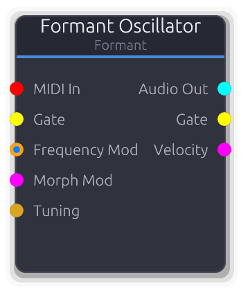
Vowel-like sounds via resonant formant filters with morph control
Produces vowel-like vocal sounds by running a carrier waveform through resonant bandpass filters tuned to formant frequencies. Pick two vowel shapes and sweep between them with the Morph knob.
The carrier waveform (Saw, Pulse, or Noise) excites the formant filter bank; Resonance controls how sharp the vowel peaks are. Morph CV adds to the property value, clamped 0.0-1.0, and bypasses the smoother when connected. The Resonance property has no CV input and applies uniformly to all formant bands.
Properties
| Name | Type | Default | Range | Help |
|---|
Frequency Oscillator | Float (Hz) · LogSlider | 220 | 20 – 5000 | Carrier oscillator pitch, used when no MIDI or FrequencyMod is connected. |
Carrier Oscillator | Enum · Dropdown | 0 | Saw / Pulse / Noise | Excitation waveform fed into the formant filter bank. Saw and Pulse are pitched; Noise is unpitched. |
Vowel A Formant | Enum · Dropdown | 0 | A / E / I / O / U | First vowel shape for the morph endpoint (A, E, I, O, U). |
Vowel B Formant | Enum · Dropdown | 3 | A / E / I / O / U | Second vowel shape for the morph endpoint (A, E, I, O, U). |
Morph Formant | Float · Slider | 0 | 0 – 1 | Crossfade between the two selected vowels. 0.0 = pure Vowel A, 1.0 = pure Vowel B. |
Resonance Formant | Float · Slider | 0.5 | 0 – 1 | Sharpness of the formant filter peaks. Higher values produce more pronounced vowel character. No CV input. |
Phase Reset Formant | Bool · Checkbox | false | | Reset phase to zero on gate/MIDI retrigger. Off by default - free-running phase lets the amp envelope shape the attack naturally. |
Inputs
MIDI In MIDI #0 - MIDI note data. Sets carrier pitch, resets phase on note-on, and drives Gate/Velocity outputs.
Gate Gate #1 - Rising edge resets the carrier phase and filter state. Shares trigger state with MIDI gate.
Frequency Mod Control (Freq) | V/Oct #2 - Pitch input. VOct offsets MIDI or the Frequency knob exponentially; ControlFreq overrides the knob in Hz.
Morph Mod Control (Norm) #3 - Adds to the Morph property value, clamped 0.0-1.0. Bypasses the smoother when connected.
Tuning Data(Tuning) #4 - Tuning configuration - overrides local divisions/octave.
Outputs
Audio Out Audio #0 - Formant-filtered audio.
Gate Gate #1 - Forwards gate events from MIDI input. Silent when MIDI is disconnected.
Velocity Control (Norm) #2 - Last MIDI note velocity as 0.0-1.0. Only emits when MIDI is connected.
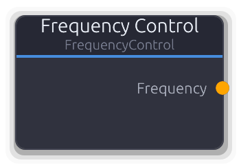
Constant frequency control source in Hz
Outputs a constant frequency value in Hz as a ControlFreq signal. Use it to drive filter cutoffs, oscillator frequencies, or any parameter that accepts ControlFreq.
Pure source node with no inputs - the output is the Frequency property value written directly to the control port each frame.
Properties
| Name | Type | Default | Range | Help |
|---|
Frequency Main | Float (Hz) · LogSlider | 1000 | 20 – 20000 | The constant Hz value emitted on the output port. |
Outputs
Frequency Control (Freq) #0 - Emits the Frequency property value as ControlFreq each frame.
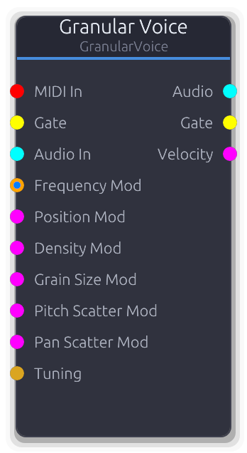
Micro-grain playback with textural, evolving sound
Granular synthesis voice that continuously fills a circular buffer from an internal oscillator or external audio, then spawns overlapping micro-grains from that buffer to produce textural, evolving timbres.
The buffer is always being written to. Grains spawn at a rate set by Density and read from a position relative to the write head (Position = 0 reads the oldest sample, 1 reads the newest). Each grain gets independent randomized pitch offset, stereo pan, and optional reverse playback. The output is the normalized sum of all active grains, divided by the number currently sounding.
Gate (from the Gate port or MIDI NoteOn) resets the write head and spawn accumulator but does not start or stop grain generation - grains run continuously regardless of gate state. MIDI also sets oscillator frequency and emits gate/velocity on the output ports.
When Source is set to Input, the Audio In signal is written into the buffer instead of the internal oscillator. The oscillator frequency is ignored in this mode, but Frequency still affects MIDI-driven pitch tracking on the output.
Properties
| Name | Type | Default | Range | Help |
|---|
Frequency Granular | Float (Hz) · LogSlider | 440 | 20 – 5000 | Base frequency of the internal oscillator when Source is Sine or Saw. Ignored when Source is Noise or Input. Overridden by MIDI note input or the Frequency Mod port. |
Grain Size Granular | Float (ms) · Slider | 30 | 1 – 100 | Duration of each grain. Determines how long each grain plays before its envelope completes. Larger values produce smoother, more overlapping textures; smaller values are clicky and percussive. |
Density Granular | Float · Slider | 10 | 1 – 50 | How many grains spawn per second. Higher density creates denser clouds with more overlap; lower density produces sparse, rhythmic textures. The pool holds up to 32 simultaneous grains - excess spawns are silently dropped. |
Position Granular | Float · Slider | 0.5 | 0 – 1 | Where in the circular buffer grains begin reading, as an offset behind the write head. 0.0 reads the oldest material in the buffer, 1.0 reads the most recently written samples. |
Position Scatter Granular | Float · Slider | 0.1 | 0 – 1 | Random spread around the grain read position. Each grain's start position is offset by a random value within this range, scaled to the buffer length. At 0.0 all grains start at the exact Position; at 1.0 they scatter across the entire buffer. |
Pitch Scatter Granular | Float (cents) · Slider | 0 | 0 – 100 | Random pitch deviation applied per grain as a playback rate offset. Each grain gets a random value in the range +/- this many cents, converted to a playback speed ratio via 2^(cents/1200). |
Pan Scatter Granular | Float · Slider | 0 | 0 – 1 | Random stereo pan assigned to each grain at spawn time. At 0.0 all grains are centered; at 1.0 grains are randomly placed anywhere in the stereo field using a constant-power pan law. |
Reverse Chance Granular | Float · Slider | 0 | 0 – 1 | Probability that each grain plays the buffer backwards. Reverse grains decrement their buffer position instead of incrementing, creating mirrored textures. |
Source Granular | Enum · Dropdown | 0 | Sine / Saw / Noise / Input | Selects what material fills the circular buffer. Sine, Saw, and Noise use the internal oscillator at the current frequency. Input writes the Audio In port signal into the buffer instead (mono-summed). |
Buffer Length Granular | Float (ms) · Slider | 100 | 50 – 2000 | Length of the internal circular buffer that source material is written into. Longer buffers allow grains to reach further back in time; shorter buffers keep the texture tightly coupled to the current input. Capped at 2 seconds (88200 samples at 44.1 kHz). |
Grain Envelope | Curve · PlainCurveEditor | Curve(Curve { keyframes: [Keyframe { time: 0.0, value: 0.0, in_tangent: 0.0, out_tangent: 0.0 }, Keyframe { time: 0.01, value: 1.0, in_tangent: 0.0, out_tangent: 0.0 }, Keyframe { time: 0.03, value: 0.0, in_tangent: 0.0, out_tangent: 0.0 }], range: Normalized }) | | Amplitude envelope shape applied to each grain. The curve is stretched to fit the grain's duration (GrainSize). The default is a short attack/decay Hann-like window. Flat or zero-duration curves produce full-amplitude grains with no windowing. |
Inputs
MIDI In MIDI #0 - MIDI note input. NoteOn sets oscillator frequency and resets the write head; NoteOff clears the triggered flag. Gate and velocity events are forwarded to the output ports.
Gate Gate #1 - Rising edge resets the write head and spawn accumulator. Does not start or stop grain generation. Falling edge clears the triggered flag so the next rising edge can re-trigger.
Audio In Audio #2 - External audio fed into the grain buffer. Only used when Source is set to Input; otherwise this port is ignored. The stereo signal is mono-summed before writing to the buffer.
Frequency Mod Control (Freq) | V/Oct #3 - Frequency control via V/Oct or ControlFreq. Priority: if MIDI is active and V/Oct is connected, they combine additively. V/Oct alone offsets the property frequency exponentially. ControlFreq replaces the frequency directly. When disconnected, the property value is used.
Position Mod Control (Norm) #4 - Overrides the Position property when connected. Smoothed to avoid zipper noise. When disconnected, the property value is used.
Density Mod Control (Norm) #5 - Overrides the Density property when connected. CV 0.0 maps to 1 grain/s, 1.0 maps to 50 grains/s. Smoothed. When disconnected, the property value is used.
Grain Size Mod Control (Norm) #6 - Overrides the Grain Size property when connected. CV 0.0 maps to 1 ms, 1.0 maps to 100 ms. Smoothed. When disconnected, the property value is used.
Pitch Scatter Mod Control (Norm) #7 - Overrides the Pitch Scatter property when connected. CV 0.0 maps to 0 cents, 1.0 maps to 100 cents. Written directly (not smoothed). When disconnected, the property value is used.
Pan Scatter Mod Control (Norm) #8 - Overrides the Pan Scatter property when connected. Smoothed. When disconnected, the property value is used.
Tuning Data(Tuning) #9 - Tuning configuration for MIDI pitch quantization. Overrides the default 12-TET divisions per octave and V/Oct offset.
Outputs
Audio Audio #0 - Stereo mix of all active grains, normalized by dividing by the number of currently sounding grains.
Gate Gate #1 - Gate events forwarded from the MIDI input. Not emitted when triggered by the Gate input port alone.
Velocity Control (Norm) #2 - MIDI velocity forwarded as normalized CV. Only emitted when MIDI input is connected.
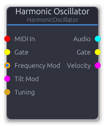
16-partial additive synthesis with spectral tilt and inharmonicity
Additive oscillator with 16 independently controllable sine partials. Sculpt timbres by drawing the harmonic spectrum directly - set each partial's amplitude and frequency ratio via node commands.
Tilt applies a dB-per-octave brightness slope across all partials: positive boosts upper partials, negative attenuates them. Tilt CV maps 0.0-1.0 to the full -1.0 to +1.0 range and overrides the property. Stretch shifts partial ratios toward inharmonic spacing using the formula `ratio * (1 + stretch * (ratio - 1) * 0.01)`, so higher partials are displaced more. The output is normalized by the count of active (non-zero amplitude) partials.
Properties
| Name | Type | Default | Range | Help |
|---|
Frequency Harmonic | Float (Hz) · LogSlider | 440 | 20 – 5000 | Fundamental pitch. All partial frequencies are multiples of this value (after stretch). |
Tilt Harmonic | Float · Knob | 0 | -1 – 1 | Spectral brightness slope at 6 dB/octave. Positive boosts upper partials, negative attenuates them. |
Stretch Harmonic | Float · Knob | 0 | 0 – 1 | Inharmonicity. Shifts partial ratios away from exact integers - higher partials are displaced more, producing bell/metallic tones. |
Phase Reset Harmonic | Bool · Checkbox | false | | Reset all partial phases to zero on gate/MIDI retrigger for consistent attack timbre. Off by default - free-running phases let the amp envelope shape the attack naturally. |
Inputs
MIDI In MIDI #0 - MIDI note data. Sets fundamental pitch, resets all 16 phases on note-on, and drives Gate/Velocity outputs.
Gate Gate #1 - Rising edge resets all 16 partial phases. Shares trigger state with MIDI gate.
Frequency Mod Control (Freq) | V/Oct #2 - Pitch input. VOct offsets MIDI or the Frequency knob exponentially; ControlFreq overrides the knob in Hz.
Tilt Mod Control (Norm) #3 - Overrides the Tilt property. 0.0 maps to -1.0 (dark), 1.0 maps to +1.0 (bright).
Tuning Data(Tuning) #4 - Tuning configuration - overrides local divisions/octave.
Outputs
Audio Audio #0 - Sum of all active partials, normalized by the count of non-zero-amplitude partials.
Gate Gate #1 - Forwards gate events from MIDI input. Silent when MIDI is disconnected.
Velocity Control (Norm) #2 - Last MIDI note velocity as 0.0-1.0. Only emits when MIDI is connected.
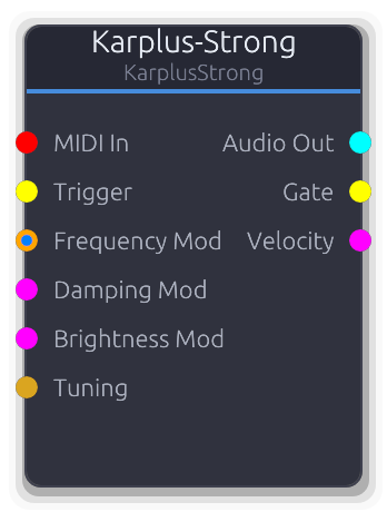
Physical modeling of plucked strings using delay line synthesis
Plucked-string physical model using delay line synthesis. A noise burst or impulse excites a tuned delay line that feeds back through a lowpass filter, producing realistic guitar, harp, and bell-like tones.
Trigger via Gate input or MIDI. MIDI NoteOn plucks at the given pitch and passes gate/velocity to the output ports. When both MIDI and V/Oct are connected, MIDI sets the base pitch and V/Oct adds an offset. V/Oct alone multiplies the Frequency property. ControlFreq directly sets frequency in Hz. Pitch is locked at trigger time in the delay line DSP.
Damping CV maps 0.0-1.0 to the 0.9-0.9999 feedback range. When disconnected, the Damping property is smoothed. Brightness CV is additive with the property value and clamped to 0.0-1.0. When disconnected, it is also smoothed.
Properties
| Name | Type | Default | Range | Help |
|---|
Frequency Oscillator | Float (Hz) · LogSlider | 440 | 20 – 5000 | Base pitch of the plucked string. Used when no MIDI, V/Oct, or ControlFreq input is connected. V/Oct alone multiplies this value. |
Damping String | Float · Slider | 0.995 | 0.9 – 0.9999 | Feedback coefficient controlling sustain length. Lower values decay quickly (staccato), higher values ring longer. Smoothed when changed via the property; overridden directly by the Damping Mod CV input. |
Brightness String | Float · Slider | 0.5 | 0 – 1 | Lowpass filter amount in the feedback loop. At 0.0 the string sounds dark and muted; at 1.0 it retains high harmonics. Smoothed when changed via the property; the Brightness Mod CV input is additive with this value. |
Pick Position String | Float · Slider | 0.5 | 0 – 1 | Where along the string the pluck occurs. At 0.5 (center), all harmonics are present. Moving toward 0.0 or 1.0 notches out different partials, changing the timbre. Only affects the excitation at trigger time. |
Excitation String | Enum · Dropdown | 0 | Noise / Impulse / FilteredNoise | Initial excitation signal injected into the delay line on trigger. Noise produces a natural pluck; Impulse gives a sharper, more percussive attack. |
Inputs
MIDI In MIDI #0 - MIDI note input. NoteOn plucks the string at the given pitch and velocity. Gate and velocity are forwarded to the output ports. When both MIDI and V/Oct are connected, MIDI sets the base pitch and V/Oct adds an offset.
Trigger Gate #1 - Rising edge excites the delay line (plucks the string). Uses the current frequency from property or CV inputs. Falling edge re-arms the trigger.
Frequency Mod Control (Freq) | V/Oct #2 - Pitch control. Accepts V/Oct (multiplied with base frequency or added to MIDI pitch) or ControlFreq (direct Hz). Priority: MIDI+V/Oct combined > V/Oct alone > ControlFreq > property.
Damping Mod Control (Norm) #3 - CV override for damping. Maps 0.0-1.0 to the 0.9-0.9999 feedback range. Overrides the smoothed property value when connected.
Brightness Mod Control (Norm) #4 - CV modulation added to the Brightness property value, clamped to 0.0-1.0. Overrides the smoothed property when connected.
Tuning Data(Tuning) #5 - Tuning configuration data. Overrides the MIDI driver's divisions-per-octave and V/Oct offset for microtonal tuning.
Outputs
Audio Out Audio #0 - Synthesized plucked-string audio (mono duplicated to stereo).
Gate Gate #1 - Gate events forwarded from MIDI input. Only emits events when MIDI In is connected.
Velocity Control (Norm) #2 - MIDI velocity as normalized CV. Only updates when a MIDI NoteOn is received.
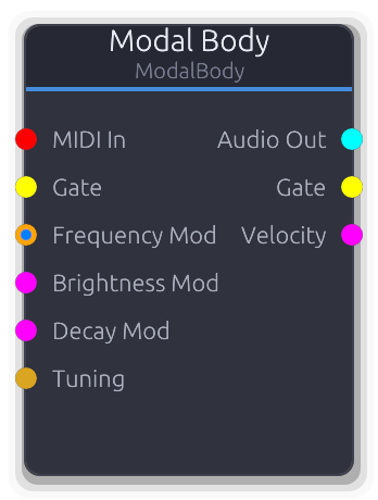
Struck body physical model - bells, marimbas, glass, metal, wood
Physical model of struck objects using a bank of damped resonators. Simulates bells, marimbas, glass, metal plates, and wood blocks.
Trigger via Gate input or MIDI. MIDI NoteOn strikes the body at the given pitch and passes gate/velocity to the output ports. When both MIDI and V/Oct are connected, MIDI sets the base pitch and V/Oct adds an offset. V/Oct alone multiplies the Frequency property. ControlFreq directly sets frequency in Hz.
Material, Brightness, Decay, and Inharmonicity are sampled at trigger time to configure the resonator bank. Brightness and Decay CV inputs are evaluated at trigger time; changing them mid-ring does not alter the decay envelope.
Properties
| Name | Type | Default | Range | Help |
|---|
Frequency Body | Float (Hz) · LogSlider | 440 | 20 – 5000 | Fundamental pitch of the struck body. Used when no MIDI, V/Oct, or ControlFreq input is connected. V/Oct alone multiplies this value. |
Material Body | Enum · Knob | 0 | 0 – 4 | Resonator preset defining partial ratios and damping characteristics. Each material has a distinct harmonic signature; sampled at trigger time. |
Brightness Body | Float · Slider | 0.8 | 0 – 1 | How much high-frequency energy the strike excites. Sampled at trigger time. Smoothed when changed via the property; the Brightness Mod CV input is additive with this value. |
Decay Body | Float · Slider | 0.5 | 0 – 1 | Resonance sustain time. Sampled at trigger time; changing it mid-ring does not alter the active decay. Overridden by the Decay Mod CV input when connected. |
Inharmonicity Body | Float · Slider | 0 | 0 – 1 | Stretches partial frequencies away from harmonic ratios. At 0.0 all partials are harmonic; increasing toward 1.0 pushes them apart, producing metallic or bell-like timbres. Sampled at trigger time. |
Inputs
MIDI In MIDI #0 - MIDI note input. NoteOn strikes the body at the given pitch and velocity. Gate and velocity are forwarded to the output ports. When both MIDI and V/Oct are connected, MIDI sets the base pitch and V/Oct adds an offset.
Gate Gate #1 - Rising edge triggers a strike using the current frequency, material, brightness, decay, and inharmonicity. Falling edge re-arms the trigger.
Frequency Mod Control (Freq) | V/Oct #2 - Pitch control. Accepts V/Oct (multiplied with base frequency or added to MIDI pitch) or ControlFreq (direct Hz). Priority: MIDI+V/Oct combined > V/Oct alone > ControlFreq > property.
Brightness Mod Control (Norm) #3 - CV modulation added to the Brightness property value, clamped to 0.0-1.0. Evaluated at trigger time.
Decay Mod Control (Norm) #4 - CV override for decay time. Replaces the Decay property value when connected. Evaluated at trigger time.
Tuning Data(Tuning) #5 - Tuning configuration data. Overrides the MIDI driver's divisions-per-octave and V/Oct offset for microtonal tuning.
Outputs
Audio Out Audio #0 - Synthesized struck-body audio (mono duplicated to stereo).
Gate Gate #1 - Gate events forwarded from MIDI input. Only emits events when MIDI In is connected.
Velocity Control (Norm) #2 - MIDI velocity as normalized CV. Only updates when a MIDI NoteOn is received.
Noise through parallel bandpass filters with per-band envelopes for percussion synthesis
Noise source routed through four parallel bandpass filters, each with its own gain and exponential decay envelope. Designed for metallic percussion: hihats, cymbals, snare noise layers.
On a gate rising edge, all four band envelopes reset to zero and filter state is cleared. Each band runs an independent exponential decay (exp(-5t)) whose duration comes from the preset's per-band decay time multiplied by the Decay Scale property. A band is considered finished when its envelope time exceeds 3.0 (approximately -65 dB). When all four bands have finished, the voice deactivates and zeros the remaining output buffer for efficiency.
The Tone property shifts all four band center frequencies together as a power-of-two multiplier (2^tone octaves). Brightness scales the filter Q values (0.5 + brightness * 2.0), so higher brightness produces tighter, more resonant bands. The output is the sum of all four filtered bands, scaled by the Accent input.
Properties
| Name | Type | Default | Range | Help |
|---|
Preset Filter Bank | Enum · Dropdown | 0 | Hihat / Snare / Cymbal / Custom | Selects the band configuration. Each preset defines four band center frequencies, Q values, gains, and decay times tuned for a specific percussion sound. Custom provides evenly spaced bands as a starting point. |
Noise Type Filter Bank | Enum · Dropdown | 0 | White / Pink / Brown | Noise color feeding all four filters. White has flat spectrum, Pink rolls off at -3 dB/octave, Brown at -6 dB/octave. Pink and Brown produce darker, less aggressive results. |
Tone Filter Bank | Float · Slider | 0 | -1 – 1 | Shifts all four band center frequencies together as a power-of-two multiplier. At -1 all bands drop an octave; at +1 they rise an octave. Frequencies are clamped to 45% of Nyquist to prevent filter instability. |
Decay Filter Bank | Float · Slider | 1 | 0.1 – 4 | Multiplier applied to all four band decay times from the preset. Lower values produce snappier hits; higher values let the bands ring out longer. |
Brightness Filter Bank | Float · Slider | 0.5 | 0 – 1 | Controls filter resonance across all bands. The preset's Q values are multiplied by (0.5 + brightness * 2.0), so at 0.0 filters are wide and dull, at 1.0 they are tight and ringing. |
Inputs
Gate In Gate #0 · required - Rising edge resets all four band envelopes and clears filter state for a clean attack. Only rising edges trigger; falling edges are ignored.
Decay CV Control (Norm) #1 - Replaces the Decay Scale property when connected. CV 0.0 maps to 0.1x, 1.0 maps to 4.0x. Sampled once per buffer. When disconnected, the property value is used.
Brightness CV Control (Norm) #2 - Replaces the Brightness property when connected. Sampled once per buffer. When disconnected, the property value is used.
Accent Control (Norm) #3 - Scales the output amplitude of all bands. Typically driven by a sequencer velocity output. Defaults to 1.0 when disconnected.
Outputs
Audio Out Audio #0 - Sum of all four filtered noise bands, each weighted by its preset gain and envelope, then scaled by Accent.
White, pink, and brown noise generator
Continuous noise source with selectable color. White has equal energy at all frequencies; pink has equal energy per octave (1/f via Voss-McCartney); brown rolls off at 1/f-squared (leaky integrator of white noise).
No MIDI or pitch input - this is a free-running generator. Amplitude CV overrides the property entirely (sets the smoother target to the CV value, ignoring the knob). When disconnected, the smoothed property value is used.
Properties
| Name | Type | Default | Range | Help |
|---|
Noise Type Generator | Enum · Dropdown | 0 | White / Pink / Brown | Noise color. Each uses a different generation algorithm with distinct spectral characteristics. |
Amplitude Generator | Float · Slider | 1 | 0 – 1 | Output level. Overridden entirely by Amplitude Mod CV when connected. |
Inputs
Amplitude Mod Control (Norm) #0 - Overrides the Amplitude property entirely - the CV value replaces the knob setting via the smoother.
Outputs
Audio Out Audio #0 - Continuous noise audio, amplitude-scaled.
Hammond-style drawbar organ with 9 harmonics and key click
Hammond-style tonewheel organ with nine drawbar harmonics and optional key click. Each drawbar controls the level of a sine partial at a specific footage ratio (16' through 1').
Gate and MIDI note-on both reset the internal oscillator phases and trigger the key click transient (edge-triggered). Key Click CV adds to the property value, clamped 0.0-1.0; it bypasses the smoother when connected. Drawbar levels are integers 0-8 mapping to the traditional Hammond registration scale.
Properties
| Name | Type | Default | Range | Help |
|---|
Frequency Oscillator | Float (Hz) · LogSlider | 440 | 20 – 5000 | Base pitch of the organ voice, used when no MIDI or FrequencyMod is connected. |
16' Sub Drawbars | Int · Slider | 8 | 0 – 8 | 16' sub-octave drawbar level (0-8). |
8' Fund Drawbars | Int · Slider | 8 | 0 – 8 | 8' fundamental drawbar level (0-8). |
5-1/3' Drawbars | Int · Slider | 8 | 0 – 8 | 5-1/3' second harmonic drawbar level (0-8). |
4' Drawbars | Int · Slider | 6 | 0 – 8 | 4' fourth harmonic drawbar level (0-8). |
2-2/3' Drawbars | Int · Slider | 0 | 0 – 8 | 2-2/3' fifth harmonic drawbar level (0-8). |
2' Drawbars | Int · Slider | 4 | 0 – 8 | 2' eighth harmonic drawbar level (0-8). |
1-3/5' Drawbars | Int · Slider | 0 | 0 – 8 | 1-3/5' tenth harmonic drawbar level (0-8). |
1-1/3' Drawbars | Int · Slider | 0 | 0 – 8 | 1-1/3' twelfth harmonic drawbar level (0-8). |
1' Drawbars | Int · Slider | 0 | 0 – 8 | 1' sixteenth harmonic drawbar level (0-8). |
Key Click Oscillator | Float · Slider | 0.3 | 0 – 1 | Percussive click on note onset, emulating tonewheel contact bounce. Fired on each gate/MIDI rising edge. |
Phase Reset Oscillator | Bool · Checkbox | false | | Reset phase to zero on gate/MIDI retrigger. Off by default - free-running phase lets the amp envelope shape the attack naturally. |
Inputs
MIDI In MIDI #0 - MIDI note data. Sets pitch, resets phases and triggers key click on note-on, and drives Gate/Velocity outputs.
Gate Gate #1 - Rising edge resets oscillator phases and fires the key click. Shares trigger state with MIDI gate.
Frequency Mod Control (Freq) | V/Oct #2 - Pitch input. VOct offsets MIDI or the Frequency knob exponentially; ControlFreq overrides the knob in Hz.
Key Click Mod Control (Norm) #3 - Adds to the Key Click property value, clamped 0.0-1.0. Bypasses the smoother when connected.
Tuning Data(Tuning) #4 - Tuning configuration - overrides local divisions/octave.
Outputs
Audio Out Audio #0 - Sum of all nine drawbar harmonics plus key click transient.
Gate Gate #1 - Forwards gate events from MIDI input. Silent when MIDI is disconnected.
Velocity Control (Norm) #2 - Last MIDI note velocity as 0.0-1.0. Only emits when MIDI is connected.
Waveform generator with frequency modulation
General-purpose waveform generator with sine, saw, square, triangle, and pulse shapes. Use as a sound source, LFO, or modulator.
Pitch priority: MIDI sets the base pitch and VOct offsets it; VOct alone scales the Frequency knob exponentially; ControlFreq overrides the knob with an absolute Hz value. Detune applies on top of all three as an exponential octave offset. Gate and MIDI note-on both reset phase on the rising edge (edge-triggered, not level-sensitive). Gate Out and Velocity Out only emit when MIDI is connected.
Properties
| Name | Type | Default | Range | Help |
|---|
Frequency Oscillator | Float (Hz) · LogSlider | 440 | 20 – 20000 | Base pitch, used when no MIDI or FrequencyMod is connected. |
Waveform Oscillator | Enum · Dropdown | 0 | Sine / Square / Sawtooth / Triangle | Output wave shape. Pulse uses the PulseWidth property; other shapes ignore it. |
Pulse Width Oscillator | Float · Slider | 0.5 | 0.01 – 0.99 | Duty cycle for the Pulse waveform (0.5 = square). Ignored by other shapes. |
Phase Reset Oscillator | Bool · Checkbox | false | | Reset phase to zero on gate/MIDI retrigger. Off by default - free-running phase lets the amp envelope shape the attack naturally. |
Inputs
MIDI In MIDI #0 - MIDI note data. Sets base pitch, resets phase on note-on, and drives Gate/Velocity outputs.
Gate Gate #1 - Rising edge resets phase for consistent attack. Shares trigger state with MIDI gate.
Frequency Mod Control (Freq) | V/Oct #2 - Pitch input. VOct offsets MIDI or the Frequency knob exponentially; ControlFreq overrides the knob in Hz.
PW Mod Control (Norm) #3 - Overrides the PulseWidth property via the smoother. Only audible with Pulse waveform.
Detune Control (Bipolar) #4 - Bipolar pitch offset applied after frequency resolution. -1.0 to +1.0 maps exponentially to -1 to +1 octaves.
Tuning Data(Tuning) #5 - Tuning configuration - overrides local divisions/octave.
Outputs
Audio Out Audio #0 - Generated waveform audio.
Gate Gate #1 - Forwards gate events from MIDI input. Silent when MIDI is disconnected.
Velocity Control (Norm) #2 - Last MIDI note velocity as 0.0-1.0. Only emits when MIDI is connected.
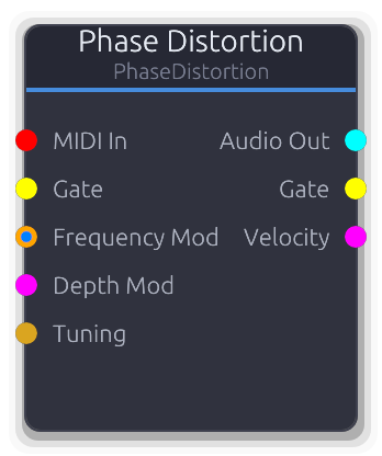
CZ-style phase distortion oscillator - saw, square, resonant, pulse timbres
Casio CZ-style oscillator that warps a sine wave's phase to produce saw, square, resonant, and pulse timbres from a single core. Sweep the Depth knob from zero (pure sine) to full for dramatically changing harmonic content.
Depth CV adds to the property value and clamps to 0.0-1.0; when disconnected the smoothed property value is used. The Mode selector chooses the phase transfer function - each mode produces a different harmonic structure at the same depth setting.
Properties
| Name | Type | Default | Range | Help |
|---|
Frequency Oscillator | Float (Hz) · LogSlider | 440 | 20 – 20000 | Base pitch, used when no MIDI or FrequencyMod is connected. |
Mode Oscillator | Enum · Dropdown | 0 | 0 – 3 | Phase transfer function shape. Each mode produces different harmonics at the same depth. |
Depth Oscillator | Float · Slider | 0.5 | 0 – 1 | Phase warping amount. 0.0 outputs a pure sine regardless of mode; 1.0 is maximum distortion. |
Phase Reset Oscillator | Bool · Checkbox | false | | Reset phase to zero on gate/MIDI retrigger. Off by default - free-running phase lets the amp envelope shape the attack naturally. |
Inputs
MIDI In MIDI #0 - MIDI note data. Sets pitch, resets phase on note-on, and drives Gate/Velocity outputs.
Gate Gate #1 - Rising edge resets phase for consistent attack. Shares trigger state with MIDI gate.
Frequency Mod Control (Freq) | V/Oct #2 - Pitch input. VOct offsets MIDI or the Frequency knob exponentially; ControlFreq overrides the knob in Hz.
Depth Mod Control (Norm) #3 - Adds to the Depth property value, clamped 0.0-1.0. Bypasses the smoother when connected.
Tuning Data(Tuning) #4 - Tuning configuration - overrides local divisions/octave.
Outputs
Audio Out Audio #0 - Phase-distorted audio.
Gate Gate #1 - Forwards gate events from MIDI input. Silent when MIDI is disconnected.
Velocity Control (Norm) #2 - Last MIDI note velocity as 0.0-1.0. Only emits when MIDI is connected.
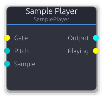
Gate-triggered sample playback with stereo output
Gate-triggered sample playback from the project library. Supports one-shot and looping modes with adjustable start/end points and pitch control.
Samples are borrowed from the resource cache each process call, so hot-swapped samples are picked up automatically. Stereo samples produce true stereo output; mono samples are duplicated to both channels. Linear interpolation is used between sample frames.
The Sample data input overrides the Sample property when connected. The Pitch input controls playback speed as a multiplier (1.0 = normal, 2.0 = double speed/octave up); negative values play in reverse. Defaults to 1.0 when disconnected.
Properties
| Name | Type | Default | Range | Help |
|---|
Mode | Enum · Dropdown | 0 | OneShot / Loop | OneShot plays the sample once and stops. Loop repeats between the Start and End positions continuously. |
Start | Float · Knob | 0 | 0 – 1 | Playback start position within the sample as a normalized fraction. Gate triggers reset playback to this position. |
End | Float · Knob | 1 | 0 – 1 | Playback end position within the sample as a normalized fraction. In OneShot mode, playback stops here. In Loop mode, playback wraps back to Start. If End <= Start, playback stops immediately. |
Sample | String · SamplePicker | "" | | Which sample from the project library to play. Overridden by the Sample data input when connected. |
Inputs
Gate Gate #0 · required - Rising edge resets the playback position to Start and begins playing. If the sample is not yet cached, the trigger is silently ignored (no crash, no playback).
Pitch Control (Bipolar) #1 - Playback speed multiplier added to the position each sample. 1.0 = normal, 2.0 = double speed / octave up, negative = reverse. Defaults to 1.0 when disconnected.
Sample Data(Sample) #2 - Data input to select a sample by resource key. Overrides the Sample property when connected.
Outputs
Output Audio #0 - Stereo audio output. Mono samples are duplicated to both channels. Outputs silence when stopped or when the sample is not cached.
Playing Gate #1 - High while the sample is actively playing. Goes low on OneShot completion or when the sample is cleared.
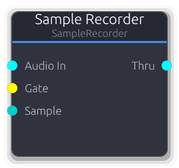
Records audio input to the project sample library
Records audio input into the project sample library. Gate-on starts recording, gate-off saves the result. Can be inserted inline without breaking the signal chain -- audio passes through unchanged to the Thru output.
Create mode adds a numbered sample each recording (e.g. "recording_001"). Overwrite mode replaces an existing sample by key. The Sample data input overrides both mode and target property: when connected, recordings always overwrite that key regardless of mode setting.
Audio is downmixed to mono internally before saving. Recording auto-stops when Max Length is reached.
Properties
| Name | Type | Default | Range | Help |
|---|
Mode | Enum · Dropdown | 0 | Create / Overwrite | Create adds a new numbered sample to the library on each recording. Overwrite replaces an existing sample selected by the Target Sample property. |
Name | String · TextInput | "recording" | | Base name for recorded samples. Auto-suffixed with a zero-padded counter (e.g. "recording_001", "recording_002"). Only visible in Create mode. |
Max Length | Float · Knob | 60 | 0.1 – 300 | Maximum recording duration. Recording auto-stops and saves when this limit is reached, even if the gate is still high. |
Target Sample | String · SamplePicker | "" | | Sample to overwrite in Overwrite mode. Only visible in Overwrite mode. Overridden by the Sample data input when connected. |
Inputs
Audio In Audio #0 · required - Stereo audio signal to record. Downmixed to mono before saving. Passed through unchanged to the Thru output regardless of recording state.
Gate Gate #1 · required - Rising edge starts recording (clears any previous buffer). Falling edge finalizes and saves the recording to the project library.
Sample Data(Sample) #2 - Data input to select a target sample key. When connected, recordings always overwrite the specified key regardless of the Mode or Target Sample property settings.
Outputs
Thru Audio #0 - Audio passthrough -- the input signal forwarded unchanged regardless of recording state. Outputs silence when Audio In is disconnected.
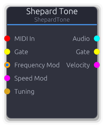
Continuously ascending/descending pitch illusion
Creates the auditory illusion of a pitch that rises (or falls) forever. Multiple sine voices spaced one octave apart are faded with a Gaussian window centered on the mid-range, so entering and leaving voices are inaudible.
The sweep position advances continuously in octaves and wraps at 1.0 (one full octave cycle). Each voice's frequency is `base_freq * 2^(voice_index + sweep_position)`. The Spread property controls the Gaussian window width in octaves - smaller values create a narrower audible band. Speed CV maps 0.0-1.0 linearly to 0.01-2.0 oct/s and overrides the property. Gate and MIDI note-on both reset sweep position and all phases.
Properties
| Name | Type | Default | Range | Help |
|---|
Frequency Shepard | Float (Hz) · LogSlider | 100 | 20 – 500 | Lowest voice frequency. All other voices are octave multiples of this value. |
Speed Shepard | Float · Slider | 0.2 | 0.01 – 2 | Sweep rate. Overridden entirely by Speed Mod CV when connected. |
Direction Shepard | Enum · Dropdown | 0 | Up / Down / Static | Sweep direction - Up, Down, or Static (no movement). |
Spread Shepard | Float · Slider | 2 | 0.5 – 4 | Width of the Gaussian amplitude window. Smaller values narrow the audible band, making the illusion more focused. |
Voices Shepard | Int · Slider | 6 | 4 – 8 | Number of octave-spaced sine voices (4–8). |
Phase Reset Shepard | Bool · Checkbox | false | | Reset phase to zero on gate/MIDI retrigger. Off by default - free-running phase lets the amp envelope shape the attack naturally. |
Inputs
MIDI In MIDI #0 - MIDI note data. Sets base pitch, resets sweep position and phases on note-on, and drives Gate/Velocity outputs.
Gate Gate #1 - Rising edge resets sweep position to zero and clears all phases. Shares trigger state with MIDI gate.
Frequency Mod Control (Freq) | V/Oct #2 - Pitch input. VOct offsets MIDI or the base frequency exponentially; ControlFreq overrides in Hz.
Speed Mod Control (Norm) #3 - Overrides the Speed property. 0.0 maps to 0.01 oct/s, 1.0 maps to 2.0 oct/s (linear).
Tuning Data(Tuning) #4 - Tuning configuration - overrides local divisions/octave.
Outputs
Audio Audio #0 - Summed and Gaussian-windowed sine voices, normalized by voice count.
Gate Gate #1 - Forwards gate events from MIDI input. Silent when MIDI is disconnected.
Velocity Control (Norm) #2 - Last MIDI note velocity as 0.0-1.0. Only emits when MIDI is connected.
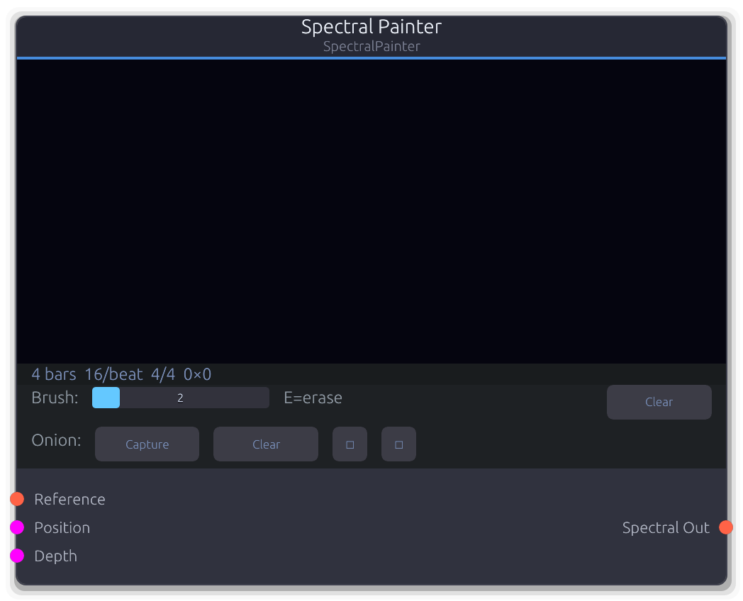
Image-based drawable spectrogram - outputs spectral data
Drawable spectrogram that converts painted pixel brightness into spectral magnitude data. Paint directly on the canvas in the UI to sculpt frequency content over time.
Each image column represents one spectral frame. The playhead advances with the transport, stepping one column per rows-per-beat subdivision, so timing is tempo-synced. Pixel Y maps to frequency on a logarithmic scale (bottom = 20 Hz, top = Nyquist). Pixel brightness (max of RGB channels) maps through a -90 dB to 0 dB range into linear magnitude.
When the Position CV is connected, it overrides the transport-driven playhead - the CV value selects the column directly as a normalized position across the canvas width. Depth CV scales all output magnitudes (defaults to 1.0 when disconnected).
The Reference input accepts spectral data from another source and renders it as an onion-skin overlay on the canvas, useful for tracing existing sounds. The onion skin can be shifted, captured, and cleared via commands. The canvas pixel buffer is persisted in the project file as an RGBA blob.
Properties
| Name | Type | Default | Range | Help |
|---|
Length | Int · SpinBox | 4 | 1 – 32 | How many bars the canvas spans. Combined with the time signature and Resolution, this determines the total number of columns (bars * beats_per_bar * rows_per_beat). Changing this resizes the canvas, preserving overlapping paint data. |
Resolution | Int · SpinBox | 16 | 4 – 64 | Temporal resolution as columns per beat. Higher values give finer time resolution but produce a wider canvas. Each column advances after (60/BPM/rows_per_beat) seconds of audio. Changing this resizes the canvas. |
Loop | Bool · Toggle | true | | Whether the playhead wraps to column 0 after reaching the last column. When off, the playhead stops at the final column and repeats that frame indefinitely. |
Inputs
Reference Spectral #0 - Spectral data rendered as an onion-skin overlay on the canvas for tracing. The reference's FFT size and sample rate are resampled to the painter's own bin grid, so any upstream FFT configuration works. Only captured while onion recording is active.
Position Control (Norm) #1 - Overrides the transport-driven playhead when connected. The CV value selects the column as a fraction of total canvas width (0.0 = first column, 1.0 = last column). Takes priority over transport position.
Depth Control (Norm) #2 - Scales all output spectral magnitudes. At 0.0 the output is silent regardless of canvas content; at 1.0 magnitudes pass through at full strength. Defaults to 1.0 when disconnected.
Outputs
Spectral Out Spectral #0 - Spectral frames derived from the painted canvas. One frame is emitted each time the playhead advances to a new column. Magnitudes are zero-phase; connect to an ISTFT or spectral processor downstream for audio output.
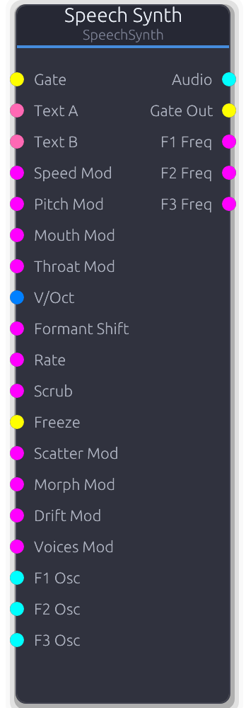
Text-to-speech formant synthesis with enhanced playback features
Formant speech synthesizer based on the SAM (Software Automatic Mouth) engine. Type text and trigger playback with a gate to produce per-sample speech audio.
Gate triggers playback from the beginning. The Loop property auto-retriggers on completion. Gate Out goes high on play start and low on finish; with Loop on, it emits off+on at each loop boundary.
CV modulation inputs (Speed/Pitch/Mouth/Throat Mod) compute effective values without mutating config properties -- property values restore automatically on disconnect. CV maps 0.0-1.0 across the full parameter range.
External oscillator inputs (F1/F2/F3 Osc) replace the built-in oscillator for that formant. SAM still controls amplitude, frequency tracking, and glottal timing.
Scrub overrides linear playback: CV directly sets frame position. An LFO on Scrub creates cyclic vowel scanning. Freeze holds the current frame while oscillator phases and glottal pulse continue running. Freeze Drift adds random formant frequency wobble while frozen, creating evolving pad textures.
V/Oct overrides glottal pitch while preserving formant shapes (vowel identity). Morph crossfades between Text A and Text B frame data (requires both text inputs connected).
Properties
| Name | Type | Default | Range | Help |
|---|
Text SAM | String · TextInput | "hello world" | | Input phrase rendered by the SAM engine. Overridden by the Text A data port when connected. |
Speed SAM | Int · Slider | 72 | 20 – 200 | Phoneme playback rate. Lower values produce slow, drawn-out speech; higher values sound rushed. Changing speed re-renders the phoneme buffer. |
Pitch SAM | Int · Slider | 64 | 0 – 255 | Voice fundamental frequency. Affects both the glottal pulse rate and the rendered phoneme data. Overridden by V/Oct input when connected (V/Oct preserves formant shapes). |
Mouth SAM | Int · Slider | 128 | 0 – 255 | Mouth cavity size shaping formant frequencies. Smaller values produce a more closed sound, larger values a more open sound. Changing this re-renders the phoneme buffer. |
Throat SAM | Int · Slider | 128 | 0 – 255 | Throat cavity size shaping resonance character. Works with Mouth to define the vocal tract. Changing this re-renders the phoneme buffer. |
Loop SAM | Bool · Toggle | false | | Auto-retrigger the phrase when it finishes. Gate Out emits off+on at each loop boundary. |
Interpolate Enhanced | Bool · Toggle | true | | Smooth transitions between phoneme frames. Off produces a classic stepped/robotic character; on yields smoother vowel transitions. |
Reverse Enhanced | Bool · Toggle | false | | Play the phoneme sequence backwards. Gate trigger starts from the end of the phrase. |
Glottal Enhanced | Curve · PlainCurveEditor | Curve(Curve { keyframes: [Keyframe { time: 0.0, value: 0.5, in_tangent: 0.0, out_tangent: 0.0 }, Keyframe { time: 0.3, value: 1.0, in_tangent: 0.0, out_tangent: 0.0 }, Keyframe { time: 1.0, value: 0.5, in_tangent: 0.0, out_tangent: 0.0 }], range: Normalized }) | | Amplitude envelope applied per glottal pulse cycle. Shapes the character of each vocal pulse. The default has a peak at 30% into the cycle and dips to 0.5 at boundaries. |
Waveform Enhanced | Enum · Dropdown | 0 | Classic / Saw / Triangle / Square / Pulse | Oscillator waveform for the glottal source. Classic uses the original SAM waveform; alternatives give different tonal characters. |
Noise Enhanced | Float · Knob | 0 | 0 – 1 | Breathy noise mixed into the voice. Adds aspiration for whispery or airy textures. |
Sub Enhanced | Float · Knob | 0 | 0 – 1 | Sub-oscillator level one octave below the voice pitch. Adds weight and body to the voice. |
Voices Unison | Int · Slider | 1 | 1 – 8 | Number of stacked unison voices. Each voice gets a staggered phase offset to avoid cancellation. Overridden by the Voices Mod CV input when connected. |
Detune Unison | Float · Knob | 0 | 0 – 1 | Pitch spread between unison voices. Voices are spread symmetrically around center, up to 50 cents at 1.0. |
Spread Unison | Float · Knob | 0 | 0 – 1 | Stereo pan spread of unison voices. Voices are distributed evenly across the stereo field, scaled by this amount. |
Scatter Playback | Float · Knob | 0 | 0 – 1 | Random per-frame playback position jitter. Overridden by the Scatter Mod CV input when connected. |
Freeze Drift Playback | Float (Hz) · Knob | 0 | 0 – 200 | Random formant frequency wobble rate while frozen. Creates evolving pad textures from a sustained vowel. Only active while Freeze is held. Overridden by the Drift Mod CV input when connected. |
Morph Playback | Float · Knob | 0 | 0 – 1 | Crossfade between Text A and Text B frame data. Requires both text inputs to be connected; with only Text A, this has no effect. Overridden by the Morph Mod CV input when connected. |
Inputs
Gate Gate #0 - Rising edge starts speech playback from the beginning (or from the end when Reverse is on). Unison voices are staggered with phase offsets to avoid cancellation.
Text A Data(Speech) #1 - Text data for phrase A. Overrides the Text property when connected; reverts to the property when disconnected.
Text B Data(Speech) #2 - Text data for phrase B, used as the morph target. Required for the Morph control to have any effect.
Speed Mod Control (Norm) #3 - CV modulation for phoneme playback speed. Maps 0.0-1.0 to the 20-200 range. Computes an effective value without mutating the property; disconnecting restores the property.
Pitch Mod Control (Norm) #4 - CV modulation for voice fundamental pitch. Maps 0.0-1.0 to the 0-255 range. Disconnecting restores the property value.
Mouth Mod Control (Norm) #5 - CV modulation for mouth cavity size. Maps 0.0-1.0 to the 0-255 range. Disconnecting restores the property value.
Throat Mod Control (Norm) #6 - CV modulation for throat cavity size. Maps 0.0-1.0 to the 0-255 range. Disconnecting restores the property value.
V/Oct V/Oct #7 - Overrides glottal pitch using V/Oct standard (0V = middle C, ~261.6 Hz). Formant shapes (vowel identity) are preserved while the fundamental pitch follows the CV.
Formant Shift Control (Norm) #8 - Shifts formant frequencies up/down independent of pitch. Maps 0.0-1.0 to -1.0..+1.0 shift range. At 0.5 (center), no shift. Defaults to no shift when disconnected.
Rate Control (Norm) #9 - Playback rate with exponential scaling: 0.0 = 0.25x, 0.5 = normal, 1.0 = 4x. Defaults to normal speed when disconnected.
Scrub Control (Norm) #10 - Overrides linear playback -- CV directly sets the frame position. An LFO on Scrub creates cyclic vowel scanning. Active even when the voice is not playing.
Freeze Gate #11 - Gate high freezes playback at the current phoneme frame. Oscillator phases and glottal pulse continue running, so the frozen vowel sustains with tonal variation. Resets to normal playback when disconnected.
Scatter Mod Control (Norm) #12 - CV override for scatter amount. Overrides the Scatter property when connected.
Morph Mod Control (Norm) #13 - CV override for A/B text morph position (0.0 = A, 1.0 = B). Overrides the Morph property when connected.
Drift Mod Control (Norm) #14 - CV override for freeze drift rate. Maps 0.0-1.0 to 0-200 Hz. Overrides the Freeze Drift property when connected.
Voices Mod Control (Norm) #15 - CV override for unison voice count (0.0 = 1 voice, 1.0 = 8 voices). Overrides the Voices property when connected.
F1 Osc Audio #16 - External oscillator replacing the first formant carrier. SAM still controls amplitude, frequency tracking, and glottal timing for this formant.
F2 Osc Audio #17 - External oscillator replacing the second formant carrier. SAM still controls amplitude, frequency tracking, and glottal timing for this formant.
F3 Osc Audio #18 - External oscillator replacing the third formant carrier. SAM still controls amplitude, frequency tracking, and glottal timing for this formant.
Outputs
Audio Audio #0 - Synthesized speech audio. Stereo when unison voices are spread, mono-duplicated otherwise.
Gate Out Gate #1 - High while speech is actively playing. With Loop on, emits off+on at each loop boundary for downstream envelope retriggering.
F1 Freq Control (Norm) #2 - First formant frequency as normalized CV (0.0-1.0 maps to 0-3000 Hz). Useful for driving external filters or visualizations.
F2 Freq Control (Norm) #3 - Second formant frequency as normalized CV (0.0-1.0 maps to 0-3000 Hz).
F3 Freq Control (Norm) #4 - Third formant frequency as normalized CV (0.0-1.0 maps to 0-3000 Hz).
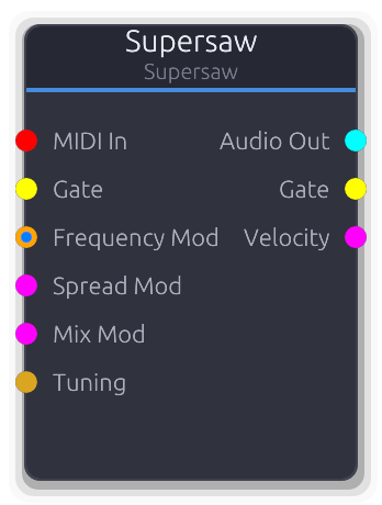
Multiple detuned sawtooth oscillators for unison lead and pad sounds
Stack of up to seven detuned sawtooth oscillators for massive unison sounds. The signature trance/EDM lead and pad tone.
Spread sets the total detuning width in cents across all voices; mix crossfades between the center voice alone (0.0) and the full chorus (1.0). When Spread CV is connected it adds `cv * 100` cents to the property value; Mix CV adds directly. Both are clamped to their property range. Pitch priority follows the standard chain: MIDI+VOct combined, VOct alone, ControlFreq, then the Frequency knob.
Properties
| Name | Type | Default | Range | Help |
|---|
Frequency Oscillator | Float (Hz) · LogSlider | 440 | 20 – 20000 | Center pitch of the unison stack, used when no MIDI or FrequencyMod is connected. |
Voices Oscillator | Int · Slider | 7 | 1 – 7 | Number of stacked saw voices (1–7). |
Spread Oscillator | Float · Slider | 25 | 0 – 100 | Total detuning width across all voices. Voices are spread symmetrically around the center pitch. |
Mix Oscillator | Float · Slider | 1 | 0 – 1 | Crossfade between center voice alone and the full detuned chorus. |
Phase Reset Oscillator | Bool · Checkbox | false | | Reset phase to zero on gate/MIDI retrigger. Off by default - free-running phase lets the amp envelope shape the attack naturally. |
Inputs
MIDI In MIDI #0 - MIDI note data. Sets pitch, resets all voice phases on note-on, and drives Gate/Velocity outputs.
Gate Gate #1 - Rising edge resets all voice phases for consistent attack. Shares trigger state with MIDI gate.
Frequency Mod Control (Freq) | V/Oct #2 - Pitch input. VOct offsets MIDI or the Frequency knob exponentially; ControlFreq overrides the knob in Hz.
Spread Mod Control (Norm) #3 - Adds cv * 100 cents to the Spread property, clamped 0-100. Bypasses the smoother when connected.
Mix Mod Control (Norm) #4 - Adds directly to the Mix property, clamped 0.0-1.0. Bypasses the smoother when connected.
Tuning Data(Tuning) #5 - Tuning configuration - overrides local divisions/octave.
Outputs
Audio Out Audio #0 - Summed and mixed supersaw audio.
Gate Gate #1 - Forwards gate events from MIDI input. Silent when MIDI is disconnected.
Velocity Control (Norm) #2 - Last MIDI note velocity as 0.0-1.0. Only emits when MIDI is connected.
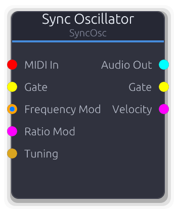
Hard-sync oscillator - aggressive, harmonically rich lead sounds
Hard-sync oscillator with a master/slave pair. The slave resets its phase every time the master completes a cycle, producing aggressive, harmonically rich timbres. Sweep the ratio for the classic sync-lead sound.
Frequency sets the master pitch; the slave runs at `frequency * ratio`. Ratio CV adds `cv * 15` to the property value, clamped 1.0-16.0, and bypasses the smoother when connected. Gate and MIDI note-on both reset master and slave phases together (edge-triggered).
Properties
| Name | Type | Default | Range | Help |
|---|
Frequency Oscillator | Float (Hz) · LogSlider | 440 | 20 – 20000 | Master oscillator pitch. The slave frequency is this times the Ratio. |
Ratio Oscillator | Float · Slider | 2 | 1 – 16 | Slave-to-master frequency multiplier. Higher values produce more harmonics due to more frequent phase resets. |
Waveform Oscillator | Enum · Dropdown | 0 | 0 – 3 | Slave oscillator waveform (Saw, Square, Sine, Triangle). |
Phase Reset Oscillator | Bool · Checkbox | false | | Reset phase to zero on gate/MIDI retrigger. Off by default - free-running phase lets the amp envelope shape the attack naturally. |
Inputs
MIDI In MIDI #0 - MIDI note data. Sets master pitch, resets both phases on note-on, and drives Gate/Velocity outputs.
Gate Gate #1 - Rising edge resets both master and slave phases. Shares trigger state with MIDI gate.
Frequency Mod Control (Freq) | V/Oct #2 - Pitch input. VOct offsets MIDI or the Frequency knob exponentially; ControlFreq overrides the knob in Hz.
Ratio Mod Control (Norm) #3 - Adds `cv * 15` to the Ratio property, clamped 1.0-16.0. Bypasses the smoother when connected.
Tuning Data(Tuning) #4 - Tuning configuration - overrides local divisions/octave.
Outputs
Audio Out Audio #0 - Slave oscillator audio, periodically reset by the master.
Gate Gate #1 - Forwards gate events from MIDI input. Silent when MIDI is disconnected.
Velocity Control (Norm) #2 - Last MIDI note velocity as 0.0-1.0. Only emits when MIDI is connected.
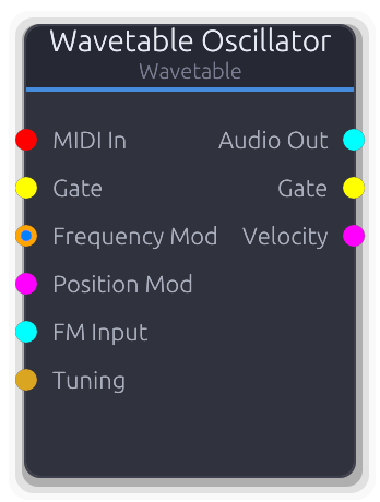
Morphable wavetable oscillator with multiple waveform frames
Scans through a table of stored waveform frames, interpolating between them for smoothly evolving timbres. Sweep the Position knob to morph through the wavetable; connect an audio signal to FM Input for linear frequency modulation.
FM is linear: the FM Input audio value is multiplied by FM Amount (in Hz) and added directly to the current frequency each sample. Position CV adds to the property value and clamps to 0.0-1.0; when disconnected, the smoothed property value is used. Detune is a static cents offset converted via `2^(cents/1200)` and applied as a final frequency multiplier.
Properties
| Name | Type | Default | Range | Help |
|---|
Frequency Oscillator | Float (Hz) · LogSlider | 440 | 20 – 20000 | Base pitch, used when no MIDI or FrequencyMod is connected. |
Wavetable Oscillator | Enum · Dropdown | 0 | SawStack / PWM / Formant / Harmonic / Digital / Vocal | Which wavetable set to load. Changing this regenerates the internal waveform data. |
Position Oscillator | Float · Slider | 0.5 | 0 – 1 | Scan position within the wavetable. 0.0 is the first frame, 1.0 is the last. |
Detune Oscillator | Float (cents) · Slider | 0 | -100 – 100 | Fine pitch offset applied as a constant multiplier via `2^(cents/1200)`. |
FM Amount Oscillator | Float (Hz) · Slider | 0 | 0 – 1000 | Scales the FM Input signal before adding to frequency. At 0 the FM Input has no effect. |
Phase Reset Oscillator | Bool · Checkbox | false | | Reset phase to zero on gate/MIDI retrigger. Off by default - free-running phase lets the amp envelope shape the attack naturally. |
Inputs
MIDI In MIDI #0 - MIDI note data. Sets pitch, resets phase on note-on, and drives Gate/Velocity outputs.
Gate Gate #1 - Rising edge resets phase for consistent attack. Shares trigger state with MIDI gate.
Frequency Mod Control (Freq) | V/Oct #2 - Pitch input. VOct offsets MIDI or the Frequency knob exponentially; ControlFreq overrides the knob in Hz.
Position Mod Control (Norm) #3 - Adds to the Position property value, clamped 0.0-1.0. Bypasses the smoother when connected.
FM Input Audio #4 - Audio-rate modulator for linear FM. Downmixed to mono, scaled by FM Amount, and added to frequency in Hz.
Tuning Data(Tuning) #5 - Tuning configuration - overrides local divisions/octave.
Outputs
Audio Out Audio #0 - Interpolated wavetable audio.
Gate Gate #1 - Forwards gate events from MIDI input. Silent when MIDI is disconnected.
Velocity Control (Norm) #2 - Last MIDI note velocity as 0.0-1.0. Only emits when MIDI is connected.
Spectral
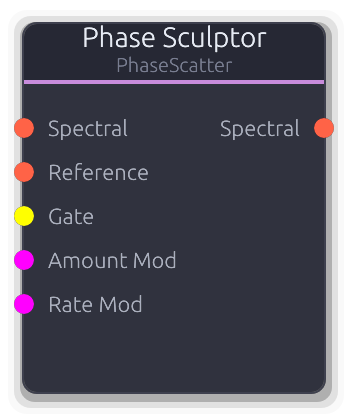
Per-bin phase manipulation - scatter, coherence, drift, freeze, transfer, smear
Per-bin phase manipulation with six modes for reshaping spectral phase relationships.
**Scatter**: replaces inst_freq with random offsets (regenerated on Gate rising edge). Destroys pitch, creates diffuse textures. **Coherence**: locks inst_freq to deterministic mathematical patterns (Zero, Linear, Alternating, Quadratic). Creates metallic, robotic, or glassy timbres. **Drift**: adds a slow random walk to inst_freq per bin, creating evolving detuned textures. Rate controls walk speed, Amount limits max offset. **FreezeDrift**: captures magnitudes on Gate rising edge (or Freeze toggle), then applies Drift to the frozen spectrum. Gate toggles freeze state. **Transfer**: crossfades inst_freq toward a Reference spectral input. Holds last received reference when disconnected. **Smear**: blurs inst_freq across neighboring bins using a triangular kernel of Width radius. Amount at 0 bypasses all modes (passthrough). The Amount Mod and Rate Mod CV inputs add to their respective knob values.
Properties
| Name | Type | Default | Range | Help |
|---|
Mode | Enum · Dropdown | 0 | Scatter / Coherence / Drift / FreezeDrift / Transfer / Smear | Selects the phase manipulation algorithm. Mode-specific properties (Pattern, Rate, Width, Freeze) are only visible when their mode is active. |
Amount | Float · Knob | 0 | 0 – 1 | Wet/dry mix for the phase manipulation. At 0 the signal passes through unchanged (bypass). At 1 the full effect applies. Crossfades between original and processed inst_freq values. |
Pattern | Enum · Dropdown | 0 | Zero / Linear / Alternating / Quadratic | Deterministic phase pattern for Coherence mode. Zero locks all bins to 0. Linear creates a slope. Alternating flips between 0 and pi. Quadratic creates accelerating curvature. |
Rate | Float · Knob | 1 | 0.01 – 10 | Random walk speed for Drift and FreezeDrift modes. Higher values cause faster phase wandering. |
Width | Int · Knob | 4 | 1 – 32 | Triangular blur kernel radius for Smear mode. Larger values average inst_freq across more neighboring bins, blurring pitch detail. |
Freeze | Bool · Toggle | false | | Manual freeze toggle for FreezeDrift mode. Captures magnitudes on activation. The Gate input also toggles freeze state independently. |
Inputs
Spectral Spectral #0 · required - Primary spectral data to manipulate. Required - produces no output without a connection.
Reference Spectral #1 · required - Phase source for Transfer mode. The last received frame's inst_freq is held when disconnected, so the transfer effect persists after unplugging.
Gate Gate #2 · required - Rising edge behavior depends on mode: Scatter regenerates random offsets, FreezeDrift toggles magnitude freeze state. Ignored in other modes.
Amount Mod Control (Norm) #3 · required - CV added to the Amount knob. Combined total is clamped 0-1.
Rate Mod Control (Norm) #4 · required - CV scaled to a 10x range and added to the Rate knob. Only affects Drift and FreezeDrift modes.
Outputs
Spectral Spectral #0 - Spectral data with manipulated instantaneous frequencies. Magnitudes are unmodified except in FreezeDrift mode where they are replaced by the frozen capture.
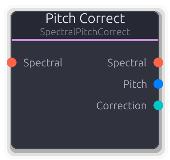
Auto-tune - pitch detection + scale snapping + spectral correction
Automatic pitch correction (auto-tune). Detects the fundamental pitch via Harmonic Product Spectrum, snaps it to the nearest note in the configured scale, and shifts the spectrum to correct.
Pitch detection runs on the first channel of the last spectral frame. The detected MIDI note is smoothed (0.7 EMA) to filter frame-to-frame jitter, then snapped to the nearest in-scale note. The correction amount is the difference between the snapped target and the smoothed detection. Speed controls convergence: at 0 the correction applies instantly (hard-tune effect), at 1 it glides very slowly (transparent correction). Notes further from the nearest scale tone than Range semitones are left uncorrected. The spectral shift uses the same bin interpolation as Spectral Shift. Detected pitch is output as V/Oct for free pitch tracking. Correction amount is output as bipolar CV (clamped to one semitone).
Properties
| Name | Type | Default | Range | Help |
|---|
Speed | Float · Knob | 0 | 0 – 1 | Correction convergence rate. At 0 the full correction applies each frame (hard-tune snap). At 1 the correction creeps toward the target over many frames (transparent glide). |
Key | Enum · Dropdown | 0 | C / C# / D / D# / E / F / F# / G / G# / A / A# / B | Root note of the target musical key. The scale mask is rotated by this offset before snapping. |
Scale | Enum · Dropdown | 0 | Chromatic / Major / Minor / Pentatonic | Scale type that determines valid snap targets. Chromatic allows all 12 semitones; Major/Minor/Pentatonic restrict to scale degrees. |
Sensitivity | Float · Knob | 0.1 | 0 – 1 | Pitch detection confidence threshold. Below this the node skips correction (outputs zero correction). Lower values allow correction of quieter or noisier signals at the risk of false detections. |
Range | Float (semi) · Knob | 2 | 0.5 – 12 | Maximum correction distance. Notes further from the nearest scale tone than this value are left uncorrected - useful for avoiding pitch jumps during large intervals. |
Output Gain | Float · Knob | 1 | 0 – 4 | Gain multiplier applied to corrected magnitudes. |
Inputs
Spectral Spectral #0 · required - Spectral data to pitch-correct. Required - produces no output without a connection. Needs valid sample_rate and fft_size for pitch detection.
Outputs
Spectral Spectral #0 - Pitch-corrected spectral data with shifted bins and scaled instantaneous frequencies.
Pitch V/Oct #1 - Detected fundamental pitch as V/Oct. Derived from the raw (unsmoothed) MIDI note: (note - 69) / 12. Useful for pitch tracking even if correction is disabled.
Correction Control (Bipolar) #2 - Smoothed correction amount as bipolar CV, clamped to the -1..+1 range (one semitone each direction). Useful for visualizing or modulating other parameters based on how far the pitch is being adjusted.
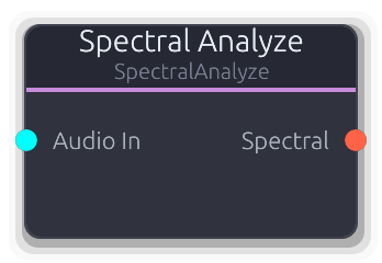
Audio to spectral data (forward FFT with phase vocoder)
Converts stereo audio into spectral data using forward FFT with phase vocoder analysis. This is the entry point for the spectral processing chain.
Connect the output to any spectral effect, then into Spectral Synthesize to return to audio. FFT Size trades frequency resolution for latency: 512 = ~11 ms, 1024 = ~21 ms, 2048 = ~43 ms, 4096 = ~85 ms at 48 kHz. Higher overlap (4x vs 2x) produces smoother results at more CPU cost. Low Freq and High Freq set the analysis range and are baked into every downstream SpectralBuffer so nodes like Spectral Split and Spectral Rotate inherit them automatically. The analyzer rebuilds when FFT Size or Overlap change.
Properties
| Name | Type | Default | Range | Help |
|---|
FFT Size | Enum · Dropdown | 2 | S512 / S1024 / S2048 / S4096 | FFT window size. Larger values give finer frequency resolution but introduce more latency. Changing this rebuilds the internal analyzer. |
Overlap | Enum · Dropdown | 1 | 2x / 4x | Overlap factor between FFT windows. 4x gives smoother magnitude/phase tracking at the cost of more CPU. Changing this rebuilds the internal analyzer. |
Low Freq | Float (Hz) · Knob | 20 | 20 – 500 | Lower edge of the analysis frequency range. Propagated to every downstream SpectralBuffer so nodes like Split and Rotate inherit the same frequency mapping. |
High Freq | Float (Hz) · Knob | 20000 | 2000 – 22000 | Upper edge of the analysis frequency range. Propagated to every downstream SpectralBuffer so nodes like Split and Rotate inherit the same frequency mapping. |
Inputs
Audio In Audio #0 · required - Stereo audio to analyze. Each channel is processed independently through the phase vocoder.
Outputs
Spectral Spectral #0 - Spectral magnitude, phase, and instantaneous frequency data. Connect to any spectral effect or directly to Spectral Synthesize.
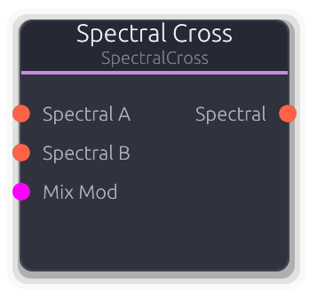
Morph or vocode between two spectral sources
Morphs between two spectral sources. In Blend mode, crossfades magnitudes, phases, and frequencies for smooth timbral transitions. In Vocoder mode, crossfades magnitudes while locking phase and frequency to input B.
Requires both inputs for crossfading. If only one input is connected, that signal passes through unmodified. Both inputs must share the same bin count - a mismatch produces silence with a logged error. Mix at 0.0 gives pure A; at 1.0 gives pure B. The Mix Mod CV input adds to the Mix knob (clamped 0-1). Output Gain is applied to the crossfaded magnitudes. In Vocoder mode, A provides the spectral envelope (magnitude) and B provides the pitch structure (phase + inst_freq), enabling spectral vocoding at full FFT resolution without band quantization.
Properties
| Name | Type | Default | Range | Help |
|---|
Mix | Float · Knob | 0.5 | 0 – 1 | Crossfade position. In Blend mode, interpolates all spectral components. In Vocoder mode, crossfades magnitudes only while phase/freq stay locked to B. |
Mode | Enum · Dropdown | 0 | Blend / Vocoder | Blend crossfades all spectral components (magnitudes, phases, inst_freq). Vocoder crossfades magnitudes but uses B's phase and frequency structure exclusively. |
Output Gain | Float · Knob | 1 | 0 – 4 | Gain multiplier applied to crossfaded magnitudes. |
Inputs
Spectral A Spectral #0 · required - First spectral source. Provides the spectral envelope (magnitudes) in Vocoder mode. Passes through if B is disconnected.
Spectral B Spectral #1 · required - Second spectral source. Provides the pitch structure (phase + inst_freq) in Vocoder mode. Passes through if A is disconnected. Must match A's bin count.
Mix Mod Control (Norm) #2 · required - CV added to the Mix knob. Combined total is clamped 0-1.
Outputs
Spectral Spectral #0 - Blended or vocoded spectral data. Uses A's metadata (FFT size, sample rate, frequency range) for the output buffer.
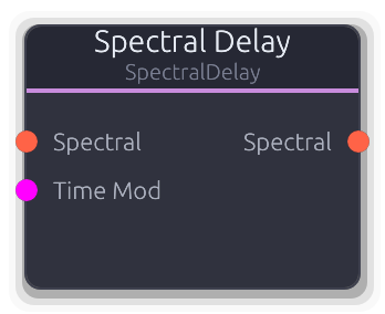
Per-bin frequency-dependent delay with feedback
Delays individual frequency bins independently, creating "frequency waterfall" effects impossible with conventional delay.
Each bin has its own delay line sized from the hop rate. The Time property sets the base delay for all bins. Spread offsets delay time linearly across the spectrum: positive values delay low frequencies more (bin_frac < 0.5 gets added time), negative values delay high frequencies more. Feedback mixes the delayed magnitude back into the delay line tail, building resonant spectral echoes (capped at 0.95 to prevent runaway). Phases and instantaneous frequencies pass through undelayed. The Time Mod CV input scales 0-1 to 0-2 seconds and adds to the Time knob. Delay lines rebuild whenever the upstream bin count or channel count changes.
Properties
| Name | Type | Default | Range | Help |
|---|
Time | Float (s) · Knob | 0.5 | 0.01 – 2 | Base delay time applied uniformly to all bins before Spread offset. Controls the center point of the delay. |
Spread | Float · Knob | 0 | -1 – 1 | Frequency-dependent delay offset. Positive values add delay to low bins and subtract from high bins; negative does the reverse. At zero, all bins share the same delay time. |
Feedback | Float · Knob | 0 | 0 – 0.95 | Delayed magnitude fed back into each bin's delay line. Creates repeating spectral echoes. Capped below 1.0 to prevent runaway buildup. |
Output Gain | Float · Knob | 1 | 0 – 4 | Gain multiplier applied to delayed magnitudes at output. |
Inputs
Spectral Spectral #0 · required - Spectral data to delay. Required - produces no output without a connection.
Time Mod Control (Norm) #1 · required - CV added to the Time knob. 0-1 maps to 0-2 seconds. Combined total is clamped to the valid delay range.
Outputs
Spectral Spectral #0 - Spectral data with per-bin delayed magnitudes. Phases and instantaneous frequencies are undelayed.
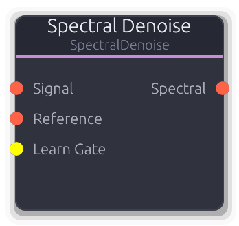
Noise profile capture + spectral subtraction
Removes steady-state noise via spectral subtraction. Capture a noise profile during a noise-only passage, then the node continuously subtracts that profile from the signal.
Workflow: connect Signal, optionally connect Reference, trigger Learn Gate (or toggle Learn) during noise-only audio, then release to apply. The noise profile is accumulated using EMA smoothing from the Reference input - or from Signal if Reference is disconnected. Subtraction always applies to Signal. Each bin's magnitude is reduced by (noise_profile * Reduction) and clamped to Floor to prevent musical noise artifacts. Before a profile is captured, Signal passes through unchanged. Phases and instantaneous frequencies are unmodified.
Properties
| Name | Type | Default | Range | Help |
|---|
Reduction | Float · Knob | 1 | 0 – 2 | How hard to subtract the learned profile. At 1.0 the full captured noise magnitude is subtracted per bin. Values above 1.0 over-subtract for aggressive cleaning. At 0.0 the profile has no effect. |
Smoothing | Float · Knob | 0.8 | 0 – 1 | EMA averaging factor during learning. Higher values weight the accumulated profile more, building a stable average over many frames. Lower values track the incoming noise faster. |
Floor | Float · Knob | 0.001 | 0 – 0.1 | Minimum magnitude after subtraction. Prevents "musical noise" artifacts from over-subtraction by clamping bins to this floor instead of zero. |
Learn | Bool · Toggle | false | | Continuous learning toggle. While on, the noise profile keeps accumulating from the Reference (or Signal). Works alongside the Learn Gate - either can activate learning independently. |
Output Gain | Float · Knob | 1 | 0 – 4 | Gain multiplier applied to denoised magnitudes after subtraction and floor clamping. |
Inputs
Signal Spectral #0 · required - Spectral signal to denoise. Subtraction is applied here. Required - produces no output without a connection. Passes through unchanged before a noise profile is learned.
Reference Spectral #1 · required - Noise reference source for learning. When disconnected, learning captures from Signal instead. Connect a separate noise-only source here for cleaner profiles.
Learn Gate Gate #2 · required - Rising edge starts learning, falling edge stops. Either the gate or the Learn toggle can activate learning independently.
Outputs
Spectral Spectral #0 - Denoised spectral data with noise profile subtracted from magnitudes. Phases and instantaneous frequencies are unmodified.
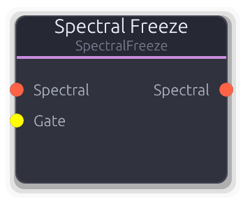
Gate captures the current spectrum and holds it indefinitely
Captures the current spectrum and holds it indefinitely, producing a sustained drone from any input.
On the rising edge of the Freeze toggle or Gate input, magnitudes from the first available frame are captured and held. While frozen, these captured magnitudes replace the live signal's magnitudes every frame. Phases and instantaneous frequencies pass through unmodified, so the downstream synthesizer's phase accumulator keeps evolving - producing a naturally shifting texture rather than a static buzz. Output Gain is applied to magnitudes during freeze; when not frozen, signal passes through unchanged. The Gate input overrides the Freeze toggle: a rising edge activates freeze regardless of the toggle state.
Properties
| Name | Type | Default | Range | Help |
|---|
Freeze | Bool · Toggle | false | | Manual freeze toggle. Captures the spectrum on the transition from off to on. The Gate input can also activate freeze. |
Output Gain | Float · Knob | 1 | 0 – 4 | Gain multiplier applied to frozen magnitudes. Has no effect when not frozen (signal passes through at unity). |
Inputs
Spectral Spectral #0 · required - Spectral data to freeze. Passes through unmodified when not frozen. Required - produces no output without a connection.
Gate Gate #1 · required - Rising edge captures the current spectrum and activates freeze. Overrides the Freeze toggle - freeze stays active as long as either the gate or toggle is high.
Outputs
Spectral Spectral #0 - Frozen spectral data: captured magnitudes with live phases and instantaneous frequencies from the input signal.
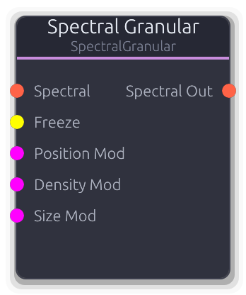
Spectral-domain granular processor with frame buffer and pitch shifting
Spectral-domain granular processor. Captures spectral frames into a circular buffer and replays them as overlapping grains with per-grain pitch shifting.
Sits in the standard Analyze -> Effect -> Synthesize chain. Grains are scheduled at the Density rate and last for Size spectral frames. Each grain reads from a jittered Position in the frame buffer with pitch shifting via bin interpolation (same technique as Spectral Shift). Multiple grains are mixed by summing magnitudes (divided by active grain count) with winner-take-all phase selection - the grain with the highest magnitude at each bin determines the output phase and instantaneous frequency. Grain envelopes use a raised cosine window controlled by Blend (0 = rectangular, 1 = maximum fade). The Freeze gate stops recording into the buffer, letting grains play from a fixed snapshot. When the buffer is empty, input passes through directly.
Properties
| Name | Type | Default | Range | Help |
|---|
Buffer | Int · SpinBox | 128 | 32 – 512 | Circular buffer capacity in spectral frames. Larger buffers hold more history for Position to scan through. Duration depends on the upstream FFT hop size. |
Density | Float (Hz) · Knob | 8 | 0.5 – 50 | Grain spawn rate. Higher values create denser clouds with more overlapping grains (up to Max Grains). |
Size | Int · SpinBox | 16 | 4 – 64 | Grain length in spectral frames. Longer grains sustain pitch and timbre; shorter grains produce more granular textures. |
Position | Float · Knob | 0 | 0 – 1 | Where in the buffer grains start reading. 0 reads from the most recently captured frames; 1 reads from the oldest. |
Pitch | Float (semi) · Knob | 0 | -24 – 24 | Per-grain pitch shift via bin interpolation. Applied as a playback rate ratio to each grain's frame read position. |
Jitter | Float · Knob | 0.1 | 0 – 1 | Randomization amount applied to each grain's start position and size at spawn time. Higher values spread grains across the buffer; 0 gives uniform placement. |
Max Grains | Int · SpinBox | 8 | 1 – 32 | Maximum simultaneous grains. Once reached, spawning pauses until active grains expire. Higher counts are more CPU intensive. |
Blend | Float · Knob | 0.5 | 0 – 1 | Grain envelope shape. At 0 grains use a rectangular window (hard edges). At 1 the raised cosine fade occupies the full grain duration for smooth overlap. |
Output Gain | Float · Knob | 1 | 0 – 4 | Gain multiplier applied to mixed grain magnitudes after grain-count normalization. |
Inputs
Spectral Spectral #0 · required - Source spectral data, continuously recorded into the frame buffer. Required - passes through directly when the buffer is empty.
Freeze Gate #1 · required - Rising edge freezes buffer recording; falling edge resumes. Grains continue playing from the frozen buffer contents.
Position Mod Control (Norm) #2 · required - CV added to the Position knob. Combined total is clamped 0-1.
Density Mod Control (Norm) #3 · required - CV scaled to the density range and added to the Density knob. Combined total is clamped to valid bounds.
Size Mod Control (Norm) #4 · required - CV scaled to a 60-frame range and added to the Size property. Combined total is clamped to valid bounds.
Outputs
Spectral Out Spectral #0 - Mixed grain output: summed magnitudes (normalized by active grain count) with winner-take-all phase selection.
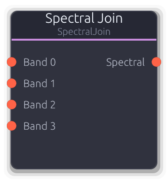
Recombines per-band spectral data from Spectral Split
Recombines per-band spectral data into a single full spectrum. The dual of Spectral Split - connect processed band outputs here to merge them back into one spectral stream for Spectral Synthesize.
For each bin, the input with the highest magnitude wins (winner-take-all): phase and instantaneous frequency come from that same input. When bands from Spectral Split do not overlap, each bin comes from exactly one input with no ambiguity. The output uses metadata (FFT size, sample rate, frequency range) from the first connected input.
Properties
| Name | Type | Default | Range | Help |
|---|
Bands | Int · Slider | 4 | 1 – 64 | How many input ports to create. Set to match Spectral Split's band count. Changes the node's input topology. |
Inputs
Band Spectral unbounded · required - Per-band spectral data from Spectral Split or per-band effects. Only connected inputs contribute; disconnected ports are skipped. When no inputs are connected, no output is produced.
Outputs
Spectral Spectral #0 - Merged full-spectrum spectral data ready for Spectral Synthesize or further spectral effects.
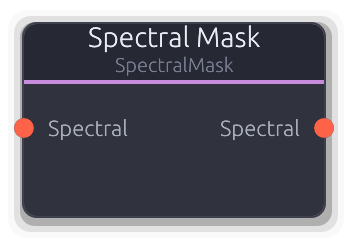
Drawable per-bin frequency filter with live spectrum overlay
Drawable frequency filter that multiplies each bin's magnitude by a user-drawn curve. Sculpt the spectrum to boost, cut, or isolate any frequency region.
The mask curve is drawn on a logarithmic frequency axis (20 Hz - 20 kHz) in the Band Curve Editor. Each FFT bin is mapped to its LogFreqT position and the curve is evaluated there, so the resolution follows the FFT size. Values above 1.0 boost that frequency region; 0.0 silences it. The curve is recomputed whenever upstream FFT parameters change (bin count, sample rate, FFT size). A live spectrum overlay displays the first channel's magnitudes in real time. Output Gain is multiplied into each bin alongside the mask value.
Properties
| Name | Type | Default | Range | Help |
|---|
Mask | Curve · BandCurveEditor | Curve(Curve { keyframes: [Keyframe { time: 0.0, value: 1.0, in_tangent: 0.0, out_tangent: 0.0 }, Keyframe { time: 1.0, value: 1.0, in_tangent: 0.0, out_tangent: 0.0 }], range: Unbounded }) | | Per-bin gain curve drawn in the Band Curve Editor. Default is flat at 1.0 (full passthrough). Values above 1.0 boost; values at 0.0 silence. The curve uses unbounded range so boosting is unrestricted. |
Output Gain | Float · Knob | 1 | 0 – 4 | Gain multiplier applied alongside the mask curve value for each bin. Stacks with the curve - use to scale overall effect intensity without redrawing. |
Inputs
Spectral Spectral #0 · required - Spectral data to filter. Required - produces no output without a connection. Provides FFT parameters used to map curve positions to frequency bins.
Outputs
Spectral Spectral #0 - Spectral data with per-bin magnitudes scaled by the mask curve and Output Gain. Phases and instantaneous frequencies are unmodified.
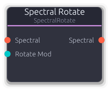
Circular bin rotation on the spectral bus
Circular rotation of FFT bins by band-aligned offsets. Creates inharmonic, metallic textures or repositions the spectrum before Spectral Split.
Uses the same log-spaced band mapping as Spectral Split (derived from the upstream SpectralBuffer's frequency range and FFT size), so rotating by N shifts by exactly N Split bands worth of bins. Rotation wraps circularly - bins shifted past Nyquist reappear at DC. Magnitudes are scaled by Output Gain during rotation. Phases and instantaneous frequencies move with their bins unmodified. The Rotate Mod input is bipolar, scaled to the band count, and added to the Rotate property. Zero rotation passes through without processing.
Properties
| Name | Type | Default | Range | Help |
|---|
Bands | Int · Slider | 8 | 2 – 64 | Number of logical bands for the rotation grid. Uses the same log-spaced mapping as Spectral Split - set to match for consistent band alignment. |
Rotate | Int · Slider | 0 | -64 – 64 | How many bands to rotate by. Positive shifts bins toward Nyquist, negative toward DC. Wraps circularly at the band count boundary. |
Output Gain | Float · Knob | 1 | 0 – 4 | Gain multiplier applied to magnitudes during rotation. |
Inputs
Spectral Spectral #0 · required - Spectral data to rotate. Required - produces no output without a connection.
Rotate Mod Control (Bipolar) #1 · required - Bipolar CV scaled to the band count and added to Rotate. -1 rotates by -N bands, +1 rotates by +N bands.
Outputs
Spectral Spectral #0 - Spectral data with circularly rotated bins, magnitudes, phases, and instantaneous frequencies.
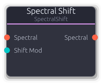
Pitch shift via spectral bin shifting (±24 semitones)
Pitch-shifts the spectrum by moving FFT bins up or down without changing playback speed.
Computes a frequency ratio from the semitone shift (2^(st/12)), then for each output bin, reads from a fractional source bin using linear interpolation on magnitudes. Instantaneous frequencies are taken from the nearest source bin and scaled by the ratio. Bins that would read beyond the spectrum stay zeroed. When shift is near zero and gain is unity, the signal passes through without processing. The Shift Mod input adds a bipolar offset scaled to the full range.
Properties
| Name | Type | Default | Range | Help |
|---|
Shift | Float (semi) · Knob | 0 | -24 – 24 | Pitch shift amount in semitones. Positive values shift up toward Nyquist; negative values shift down toward DC. |
Output Gain | Float · Knob | 1 | 0 – 4 | Gain multiplier applied to shifted magnitudes. Applied during the bin interpolation pass. |
Inputs
Spectral Spectral #0 · required - Spectral data to pitch-shift. Required - produces no output without a connection.
Shift Mod Control (Bipolar) #1 · required - Bipolar CV added to the Shift value. -1 maps to -24 st, +1 maps to +24 st. Combined total is clamped to the full range.
Outputs
Spectral Spectral #0 - Pitch-shifted spectral data with interpolated magnitudes and scaled instantaneous frequencies.
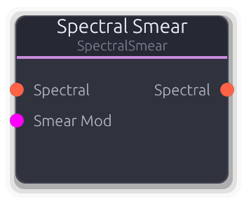
Temporal magnitude smoothing for ambient textures
Applies temporal smoothing to per-bin magnitudes, blurring the spectrum over time. Low values add subtle sustain; high values create evolving ambient washes.
Uses an exponential moving average per bin: each frame blends the stored average with the incoming magnitude using the Smear factor as the EMA coefficient. At maximum, approaches infinite hold similar to Spectral Freeze but with gradual accumulation rather than a hard capture. When Smear is near zero, averages are reset and signal passes through. Phases and instantaneous frequencies are unmodified. The Smear Mod CV input adds to the Smear knob value (clamped 0-1).
Properties
| Name | Type | Default | Range | Help |
|---|
Smear | Float · Knob | 0 | 0 – 1 | EMA smoothing coefficient. At 0, signal passes through unmodified. Higher values hold spectral energy longer, building up ambient textures. |
Output Gain | Float · Knob | 1 | 0 – 4 | Gain multiplier applied to smoothed magnitudes each frame. |
Inputs
Spectral Spectral #0 · required - Spectral data to smooth. Required - produces no output without a connection.
Smear Mod Control (Norm) #1 · required - CV added to the Smear knob value. Combined total is clamped 0-1.
Outputs
Spectral Spectral #0 - Temporally smoothed spectral data with EMA-blended magnitudes and original phases.
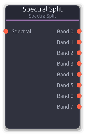
Partitions spectral data into N frequency bands
Partitions spectral data into N logarithmically-spaced frequency bands. Patch any effect between Split and Join to make it spectral - delay becomes spectral delay, distortion becomes spectral distortion.
Each output carries a SpectralBuffer with only that band's bins populated (all others zeroed). Pure spectral routing - no FFT/IFFT happens here. The typical chain is Spectral Analyze -> Split -> per-band effects -> Join -> Spectral Synthesize. Band boundaries use log-frequency spacing derived from the upstream Analyze node's Low Freq, High Freq, and FFT Size. Inherent latency equals the upstream FFT size in samples (~21 ms at 1024/48 kHz).
Properties
| Name | Type | Default | Range | Help |
|---|
Bands | Int · Slider | 8 | 2 – 64 | How many output ports to create. More bands give finer frequency control at the cost of more patching. Changes the node's output topology and recomputes log-spaced bin boundaries. |
Inputs
Spectral Spectral #0 · required - Full-spectrum spectral data from Spectral Analyze or another spectral effect. Provides bin count, frequency range, and sample rate used to compute band boundaries.
Outputs
Band Spectral unbounded - One output per band, each containing only the bins for that frequency region. Connect to per-band effects, then into Spectral Join to recombine.
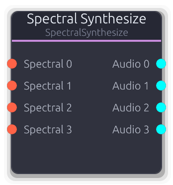
Spectral data to audio (inverse FFT with phase vocoder)
Converts spectral data back into stereo audio using inverse FFT with overlap-add reconstruction. This is the exit point of the spectral processing chain.
Accepts one or many spectral inputs and produces a matching number of stereo audio outputs. Each input/output pair runs its own synthesizer, but all share FFT plans for efficiency. Synthesizers are lazily created on first data - FFT parameters (size, overlap) come from the upstream SpectralBuffer. Set the Channels property to match the number of spectral inputs you intend to connect.
Properties
| Name | Type | Default | Range | Help |
|---|
Channels | Int · Slider | 4 | 1 – 64 | Number of spectral input / audio output port pairs. Set to match the number of upstream spectral sources. Controls both input and output topology. |
Output Gain | Float · Knob | 1 | 0 – 4 | Gain multiplier applied to all reconstructed audio samples after IFFT. Useful for compensating level differences introduced by spectral effects. |
Inputs
Spectral Spectral unbounded · required - Spectral data from Spectral Analyze, spectral effects, or Spectral Split bands. Each connected input creates a dedicated synthesizer.
Outputs
Audio Audio unbounded - Reconstructed stereo audio. Output index matches the corresponding spectral input index.
Utility
Converts audio-rate signals to control-rate by sampling first sample of buffer
Samples the first stereo frame of each audio buffer, downmixes to mono ((L+R)/2), and outputs the result as a control-rate value.
Only the first sample of each buffer is used -- subsequent samples are ignored. The output updates once per buffer at whatever the graph's block size is. Useful for driving parameters from audio-rate signals like envelopes or LFOs running through the audio bus.
Inputs
Audio In Audio #0 · required - Stereo audio signal to sample.
Outputs
Control Out Control (Norm) #0 - Mono-downmixed amplitude as a normalized control value.
Single trigger → N evenly-spaced trigger pulses with acceleration
Fires a rapid burst of gate pulses from a single trigger.
Each rising edge on Trigger starts a burst of Count pulses at the configured Rate. Pulses have a 50% duty cycle. Acceleration divides each successive interval: >1.0 speeds up (accelerando), <1.0 slows down (ritardando), 1.0 is even spacing. A retrigger during an active burst restarts from the beginning. The minimum interval is clamped at 5 ms to prevent degenerate pulse widths.
Properties
| Name | Type | Default | Range | Help |
|---|
Count | Int · SpinBox | 4 | 1 – 32 | Number of pulses per burst (1--32). |
Rate | Float (Hz) · LogSlider | 10 | 1 – 100 | Base pulse rate in Hz (1--100 Hz). |
Accel | Float · Knob | 1 | 0.25 – 4 | Divides each successive interval. >1.0 accelerates (shorter intervals), <1.0 decelerates (longer intervals). |
Inputs
Trigger Gate #0 · required - Rising edge starts a new burst.
Outputs
Gate Gate #0 - Burst pulse train output.
Audio clipping and saturation with hard and soft modes
Clips or saturates a stereo audio signal. Each stereo channel is processed independently per sample.
In Hard mode the signal hits a symmetric brick wall at +/- threshold. In Soft mode tanh saturation provides a warmer overdrive character that smoothly approaches the ceiling. The threshold is per-sample smoothed to prevent clicks when adjusted. Lower threshold values clip harder.
Properties
| Name | Type | Default | Range | Help |
|---|
Threshold Clipping | Float · Slider | 0.95 | 0.1 – 1 | Clipping ceiling (0.1--1.0). Lower values clip harder. |
Mode Clipping | Enum · Dropdown | 1 | Hard / Soft | Hard (brick wall) or Soft (tanh saturation). |
Inputs
Audio In Audio #0 · required - Stereo audio signal to clip.
Outputs
Audio Out Audio #0 - Clipped stereo audio.
Generates precise timing gate signals
Free-running clock source that emits gate pulses at a configurable frequency.
Each cycle begins with the gate going high for the pulse width duration, then low for the remainder of the period. The pulse width is capped at 90% of the period to guarantee a falling edge even at high frequencies. A Rate Mod CV replaces the Frequency property with an exponential mapping from 0--1 across 0.01--1000 Hz. A Reset rising edge zeros the phase for sync.
Properties
| Name | Type | Default | Range | Help |
|---|
Frequency Clock | Float (Hz) · LogSlider | 1 | 0.01 – 1000 | Clock rate in Hz (0.01--1000 Hz). |
Pulse Width Clock | Float (ms) · Slider | 10 | 1 – 100 | Duration of each high pulse in milliseconds (1--100 ms). |
Inputs
Rate Mod Control (Norm) #0 - Replaces the Frequency property with an exponential mapping: 0.0 = 0.01 Hz, 1.0 = 1000 Hz.
Reset Gate #1 - Rising edge resets the clock phase to zero.
Outputs
Gate Out Gate #0 - Clock pulse output.
Divide or multiply incoming clock triggers by an integer ratio
Divides or multiplies an incoming clock by an integer ratio.
In Divide mode, a rising edge passes through every N-th input trigger; falling edges only pass when the counter is at zero. In Multiply mode, the node measures the period between incoming triggers and emits N evenly-spaced subdivisions within that period, each with a 50% duty cycle. The first incoming trigger establishes the period -- no subdivisions are emitted until the second trigger arrives. A Reset rising edge zeros the counter.
Properties
| Name | Type | Default | Range | Help |
|---|
Mode | Enum · Dropdown | 0 | Divide / Multiply | Divide (slow down) or Multiply (speed up) the clock. |
Ratio | Int · SpinBox | 2 | 1 – 32 | Division or multiplication factor (1--32). |
Inputs
Clock Gate #0 · required - Incoming clock trigger to divide or multiply.
Reset Gate #1 - Rising edge resets the internal counter.
Outputs
Gate Gate #0 - Divided or multiplied clock output.
Threshold comparison on continuous signals, outputs gate
Compares a continuous control signal against a threshold and outputs a gate. Schmitt trigger hysteresis prevents chattering.
The hysteresis creates a dead band: for > and >= modes, the gate turns on when the input exceeds threshold + hysteresis/2 and stays on until it drops below threshold - hysteresis/2 (and vice versa for < and <=). A Threshold Mod CV replaces the property value when connected. The input defaults to 0.0 when disconnected.
Properties
| Name | Type | Default | Range | Help |
|---|
Compare | Enum · Dropdown | 0 | > / < / >= / <= | Comparison operator (>, <, >=, <=). |
Threshold | Float · Slider | 0.5 | -1 – 1 | Reference level for comparison (-1.0--1.0). |
Hysteresis | Float · Knob | 0.01 | 0 – 0.2 | Dead-band width to prevent chattering (0.0--0.2). |
Inputs
Input Control (Bipolar) #0 · required - Signal to compare against the threshold.
Threshold Control (Bipolar) #1 - Replaces the Threshold property value when connected.
Outputs
Gate Gate #0 - High when the comparison is true, low otherwise.
Outputs a constant value as configuration data
Outputs a fixed value as structured data on every buffer.
Set the type (Number, String, Bool, FilePath, or Resource) and the corresponding value, then wire the Data output to any node that expects configuration. Changing the type resets the value to a default for that type. The output is a boxed `ConstantValue` enum on a Data port.
Properties
| Name | Type | Default | Range | Help |
|---|
Type | Enum · Dropdown | 0 | Number / String / Bool / FilePath / Resource | Which data type to output (Number, String, Bool, FilePath, Resource). |
Number | Float · SpinBox | 0 | -1000000 – 1000000 | Numeric constant when type is Number. |
String | String · TextInput | "" | | Text constant when type is String. |
Bool | Bool · Checkbox | false | | Boolean constant when type is Bool. |
File Path | String · TextInput | "" | | File path constant when type is FilePath. |
Resource | String · Dropdown | "" | | Project resource reference when type is Resource. |
Outputs
Data Out Data(Unknown) #0 - The constant value as structured data.
Converts between control signal types with proper range mapping
Accepts any control-family signal and produces correctly converted outputs for every signal type simultaneously.
The node detects the source port type at process time and applies proper conversion math. Norm uses linear 0--1 mapping; Bipolar maps -1..1 to 0..1 linearly; ControlFreq uses log-scale normalization across 20--20000 Hz. Generic Control is treated as already 0--1 for Norm and clamped to -1..1 for Bipolar.
Audio output is dual-mono stereo from the normalized value. V/Oct is derived by converting through frequency first (relative to middle C at 261.63 Hz). Gate goes high when the normalized value reaches 0.5 and low when it drops below, with edge detection. The raw Control output passes through unchanged.
Inputs
Input Control | Control (Norm) | Control (Bipolar) | Control (Freq) #0 · required - Any control-family signal (Control, Norm, Bipolar, Freq).
Outputs
Control Control #0 - Raw input value passed through with no conversion.
Norm Control (Norm) #1 - Normalized 0.0--1.0 output.
Bipolar Control (Bipolar) #2 - Bipolar -1.0--1.0 output.
Freq Control (Freq) #3 - Frequency in Hz. Norm/Bipolar sources are exponentially mapped across the audible range; ControlFreq is clamped; generic Control is treated as Hz and clamped.
Audio Audio #4 - Dual-mono stereo audio from the normalized value.
VOct V/Oct #5 - V/Oct pitch CV derived from frequency conversion.
Gate Gate #6 - Gate high when normalized value >= 0.5.
Maps control signals from one range to another
Linearly rescales a control signal from one range to another.
The input value is normalized against the Input Min/Max range, then mapped to the Output Min/Max range. If the input range has zero width the output defaults to Output Min. With Clamp enabled, the output is constrained to the output bounds. With Clamp off, values outside the input range extrapolate beyond the output range. Inverted ranges (min > max) are supported for reverse mapping.
Properties
| Name | Type | Default | Range | Help |
|---|
Input Min Input Range | Float · Slider | 0 | -1000 – 1000 | Expected minimum of the incoming signal. |
Input Max Input Range | Float · Slider | 1 | -1000 – 1000 | Expected maximum of the incoming signal. |
Output Min Output Range | Float · Slider | 0 | -10000 – 10000 | Desired minimum of the output signal. |
Output Max Output Range | Float · Slider | 1 | -10000 – 10000 | Desired maximum of the output signal. |
Clamp | Bool · Toggle | true | | When enabled, constrains output to the output min/max bounds. |
Inputs
Control In Control #0 · required - Control signal to remap.
Outputs
Control Out Control #0 - Rescaled control signal.
Two-input control math: add, subtract, multiply, min, max, crossfade
Two-input math on control-rate signals. Combine, compare, or crossfade a pair of normalized control values.
Disconnected inputs default to 0.0. Add and Subtract results are clamped to 0.0--1.0. Multiply, Min, and Max are unclamped. Crossfade uses the Mix property: 0.0 = all A, 1.0 = all B. Unlike SignalMathNode this operates at control rate (one value per buffer, no per-sample smoothing on Mix).
Properties
| Name | Type | Default | Range | Help |
|---|
Operation Math | Enum · Dropdown | 0 | Add / Subtract / Multiply / Min / Max / Crossfade | Math operation to apply (Add, Subtract, Multiply, Min, Max, Crossfade). |
Mix Math | Float · Slider | 0.5 | 0 – 1 | Crossfade balance between A and B (0.0 = all A, 1.0 = all B). |
Inputs
A Control (Norm) #0 - First control operand (0.0--1.0).
B Control (Norm) #1 - Second control operand (0.0--1.0).
Outputs
Out Control (Norm) #0 - Result of the selected operation (0.0--1.0).
Scales normalized control (0-1) to frequency range in Hz
Scales a normalized 0--1 control value to a frequency range in Hz using linear interpolation between Min Hz and Max Hz.
The input is clamped to 0--1 before scaling. Min Hz must be less than Max Hz. Useful for converting LFO or knob output into a frequency modulation signal for oscillators and filters.
Properties
| Name | Type | Default | Range | Help |
|---|
Min Hz Range | Float (Hz) · LogSlider | 20 | 20 – 20000 | Lower bound of the output frequency range (20--20000 Hz). |
Max Hz Range | Float (Hz) · LogSlider | 20000 | 20 – 20000 | Upper bound of the output frequency range (20--20000 Hz). |
Inputs
Control In Control (Norm) #0 · required - Normalized control input (0.0--1.0).
Outputs
Frequency Out Control (Freq) #0 - Scaled frequency in Hz.
Smooth control signal transitions with independent rise and fall rates
Rate-limiter for control signals with independent rise and fall times.
Smooths abrupt parameter changes into gradual transitions. The slew operates at control rate (once per buffer): the maximum change per buffer is buffer_duration / slew_time. Rise time governs upward movement, fall time governs downward. At 0 seconds the output tracks the input instantly. Output is clamped to 0--1. On the first buffer, the output jumps to the input value with no slew. Useful for lag processing, portamento on control values, or envelope-like shaping of knob movements.
Properties
| Name | Type | Default | Range | Help |
|---|
Rise Time Timing | Float (s) · Slider | 0.1 | 0 – 10 | Time to slew from 0 to 1 in seconds (0--10 s). |
Fall Time Timing | Float (s) · Slider | 0.1 | 0 – 10 | Time to slew from 1 to 0 in seconds (0--10 s). |
Inputs
Control In Control (Norm) #0 · required - Control signal to smooth.
Outputs
Control Out Control (Norm) #0 - Smoothed control output (0.0--1.0).
Smooth blend between two audio inputs
Smooth blend between two audio inputs with per-sample smoothing on the position parameter.
Linear mode: gain_A = 1-pos, gain_B = pos. Equal-power mode uses sin/cos curves for constant loudness across the crossfade range. A Position Mod CV replaces the property value when connected; when disconnected the smoother tracks the property. Disconnected audio inputs contribute silence, so a single connected input acts as a fade in/out. Both inputs disconnected reports Silent.
Properties
| Name | Type | Default | Range | Help |
|---|
Position | Float · Slider | 0 | 0 – 1 | Crossfade position (0.0 = A, 1.0 = B). |
Curve | Enum · Dropdown | 0 | Linear / EqualPower | Crossfade curve shape. |
Inputs
Input A Audio #0 - Audio input A (heard at Position 0.0).
Input B Audio #1 - Audio input B (heard at Position 1.0).
Position Control (Norm) #2 - CV control over crossfade position (0.0 = A, 1.0 = B).
Outputs
Output Audio #0 - Blended audio output.
Drawable signal→signal transfer function for waveshaping and CV remapping
Drawable signal-to-signal transfer function. Maps audio or control input through a user-drawn spline curve.
For audio, each sample is driven by InputGain, clamped to -1..1, normalized to 0..1 for the curve lookup, then denormalized back to -1..1 and scaled by OutputGain. The Mix knob blends the shaped (wet) signal with the original (dry) per-sample with smoothing.
For control, the input is evaluated through the curve once per buffer without smoothing. InputGain and OutputGain only affect the audio path. Both audio and control paths can operate simultaneously through the same curve. A Mix CV overrides the property value when connected.
Properties
| Name | Type | Default | Range | Help |
|---|
Curve | Curve · PlainCurveEditor | Curve(Curve { keyframes: [Keyframe { time: 0.0, value: 0.0, in_tangent: 0.0, out_tangent: 1.0 }, Keyframe { time: 1.0, value: 1.0, in_tangent: 1.0, out_tangent: 0.0 }], range: Normalized }) | | The transfer function curve (0→1 input, 0→1 output). |
Input Gain Drive | Float · Knob | 1 | 0.1 – 4 | Pre-curve gain - drives the signal harder into the curve. |
Output Gain Drive | Float · Knob | 1 | 0.1 – 4 | Post-curve gain - compensates for level changes. |
Mix Mix | Float (%) · Slider | 1 | 0 – 1 | Dry/wet blend (0.0 = dry, 1.0 = fully shaped). |
Inputs
Audio Audio #0 · required - Audio signal for per-sample waveshaping.
Control Control (Norm) #1 · required - Control signal for CV remapping (evaluated once per buffer).
Mix CV Control (Norm) #2 · required - Modulates dry/wet mix.
Outputs
Audio Audio #0 - Shaped audio output.
Control Control (Norm) #1 - Shaped control output.
Comprehensive debug node for testing all proc macro features
Diagnostic probe for inspecting signals in the graph. Accepts any signal type on unbounded inputs.
In Passthrough mode, the first connected input is forwarded to the output unchanged; remaining inputs are ignored. In Monitor and Analyze modes, all inputs are consumed (force-pulled to keep upstream nodes processing) but the output is silence. When Enabled is on, the node periodically emits a `debug_tick` custom event and increments the read-only EmitCount property at the configured interval. The output port type locks to the first connected input type.
Properties
| Name | Type | Default | Range | Help |
|---|
Inputs | Int · Slider | 4 | 1 – 64 | How many input ports to create. |
Emit Interval Timing | Float (s) · Knob | 1 | 0 – 10 | Seconds between diagnostic event emissions. Set to 0 to disable periodic emission entirely. |
Emit Count Stats | Int · Slider | 0 | 0 – 1000000 | Read-only counter of emitted diagnostic events. |
Enabled Control | Bool · Toggle | true | 0 – 1 | Toggle diagnostic emission on/off. |
Mode Control | Enum · Dropdown | 0 | Passthrough / Monitor / Analyze | Passthrough forwards the first connected input to the output. Monitor and Analyze consume all inputs but output silence. |
Inputs
Input Audio | Control | Control (Norm) | Control (Bipolar) | Control (Freq) | MIDI | Gate | V/Oct | Data(Unknown) | Image unbounded - Any signal type -- connect as many sources as needed.
Outputs
Output Audio | Control | Control (Norm) | Control (Bipolar) | Control (Freq) | MIDI | Gate | V/Oct | Data(Unknown) | Image #0 - First input forwarded (Passthrough mode) or silence (Monitor/Analyze).
Detects and logs sudden jumps in audio signal (clicks/pops)
Monitors an audio stream for sudden sample-to-sample jumps that indicate clicks, pops, or buffer-boundary artifacts.
Computes the absolute difference between consecutive samples on each stereo channel independently and reports when the larger of the two exceeds the threshold. When Log to Console is enabled, each detection emits a tracing warning with the sample offset and per-channel deltas. Pass Through controls whether audio reaches the output or is replaced with silence, allowing silent monitoring. Internal counters track total detections and maximum discontinuity magnitude.
Properties
| Name | Type | Default | Range | Help |
|---|
Threshold | Float · Slider | 0.1 | 0.001 – 1 | Sample-to-sample jump size that triggers a warning (0.001--1.0). |
Log to Console | Bool · Toggle | true | | When enabled, logs each detected discontinuity to the console. |
Pass Through | Bool · Toggle | true | | When enabled, forwards audio to the output; when off, outputs silence. |
Inputs
Audio In Audio #0 · required - Audio signal to monitor for discontinuities.
Outputs
Audio Out Audio #0 - Pass-through audio (or silence if pass-through is off).
Evenly distributed rhythmic patterns via the Bjorklund algorithm
Distributes N hits as evenly as possible across M steps using the Bjorklund algorithm.
On each clock rising edge the pattern advances one step. If the current step is a hit and the gate is low, a rising edge is emitted. On a clock falling edge the gate always goes low. This means the output gate width matches the input clock pulse width. A Reset rising edge returns the step counter to zero. Rotation shifts the pattern start position. The pattern recomputes whenever Hits, Steps, or Rotation changes.
Properties
| Name | Type | Default | Range | Help |
|---|
Hits | Int · SpinBox | 3 | 0 – 32 | Number of active pulses in the pattern (0--32). |
Steps | Int · SpinBox | 8 | 1 – 32 | Total steps in the pattern cycle (1--32). |
Rotation | Int · SpinBox | 0 | 0 – 31 | Rotate the pattern start position (0--31 steps). |
Inputs
Clock Gate #0 · required - Clock input -- each rising edge advances the pattern one step.
Reset Gate #1 - Rising edge resets the step counter to zero.
Outputs
Gate Gate #0 - Gate high on hit steps, low on rests.
Gate-triggered audio fade in/out
Smoothly fades audio in and out with independent fade times.
Two trigger modes: the Level input (ControlNorm) takes priority when connected -- values at or above the Gate Threshold trigger fade in, below triggers fade out. This lets Arranger track outputs wire directly without a converter. When Level is not connected, the Gate input drives the fade via edge detection.
The fade is linear per-sample: each sample advances the internal gain by 1/(fade_time * sample_rate). When fully faded out with the gate low, the node reports Silent for optimization.
Properties
| Name | Type | Default | Range | Help |
|---|
Fade In | Float (ms) · Knob | 100 | 0.5 – 5000 | Fade in time in milliseconds. |
Fade Out | Float (ms) · Knob | 100 | 0.5 – 5000 | Fade out time in milliseconds. |
Gate Threshold | Float · Knob | 0.5 | 0 – 1 | Threshold for the Level input. Values at or above this trigger fade in; below triggers fade out. Only used when Level is connected. |
Inputs
Audio In Audio #0 · required - Audio signal to fade.
Gate Gate #1 - Gate input - rising edge triggers fade in, falling edge triggers fade out. Ignored when the Level input is connected.
Level Control (Norm) #2 - ControlNorm level input. When connected, overrides the Gate input. Values at or above the Gate Threshold trigger fade in; below triggers fade out. Wire Arranger track outputs here directly.
Outputs
Audio Out Audio #0 - Faded audio output.
Toggles between two audio inputs on gate trigger with smooth crossfading
Routes one of two audio inputs to the output, toggling on each gate trigger with smooth crossfading.
Gate priority: Set forces A (active_b = false), Reset forces B (active_b = true), Toggle flips the state. All three are evaluated per buffer in that order. A Crossfade CV overrides the toggle state entirely when connected: 0.0 = A, 1.0 = B, with intermediate values blending. The State gate output tracks the toggle state (high = B active). Disconnected audio inputs contribute silence.
Properties
| Name | Type | Default | Range | Help |
|---|
Crossfade Routing | Float (ms) · Slider | 5 | 0 – 1000 | Transition time between A and B in milliseconds (0--1000 ms). |
Inputs
A Audio #0 - First audio source (selected when toggle is off).
B Audio #1 - Second audio source (selected when toggle is on).
Toggle Gate #2 - Rising edge flips between A and B.
Set Gate #3 - Rising edge forces output to A (clears active_b).
Reset Gate #4 - Rising edge forces output to B (sets active_b).
Crossfade Control (Norm) #5 - CV mix override (0.0 = A, 1.0 = B). Overrides toggle state.
Outputs
Audio Audio #0 - Crossfaded audio from A and B.
State Gate #1 - Gate high when B is active, low when A is active.
Amplify or attenuate audio signal
Simple volume control for a stereo audio signal with per-sample smoothing to avoid clicks.
The Gain Mod CV input, when connected, replaces the property value: ControlNorm 0.0--1.0 maps to gain 0.0--2.0. When disconnected the smoother tracks the property value. Both paths go through the same smoother so transitions are always clean.
Properties
| Name | Type | Default | Range | Help |
|---|
Gain | Float · Knob | 1 | 0 – 4 | Gain multiplier (0.0 = silence, 1.0 = unity, 4.0 = +12 dB). |
Inputs
Audio In Audio #0 · required - Stereo audio signal to amplify or attenuate.
Gain Mod Control (Norm) #1 - Replaces the property value. 0.0 = silence, 0.5 = unity, 1.0 = 2x.
Outputs
Audio Out Audio #0 - Gained stereo audio.
Converts gate events to Audio or Control signals based on output connection.
Converts gate events into Audio, Control, or Gate output depending on what the output port is connected to.
The conversion target is set automatically when the output is wired. Audio mode produces stereo dual-mono 0.0/1.0 steps with instant transitions on gate edges. Control mode applies one-pole attack/release smoothing from 0.0 to 1.0 -- the envelope advances by one sample per buffer, so attack/release times interact with buffer size at very short settings. Gate mode passes events through unchanged. When disconnected, the output reverts to accepting any of the three types.
Properties
| Name | Type | Default | Range | Help |
|---|
Attack Envelope | Float (ms) · Slider | 5 | 0.1 – 1000 | Rise time for Control output. Only affects Control mode. |
Release Envelope | Float (ms) · Slider | 100 | 1 – 5000 | Fall time for Control output. Only affects Control mode. |
Inputs
Gate In Gate #0 · required - Gate events to convert.
Outputs
Output Audio | Control | Gate #0 - Converted signal (Audio, Control, or Gate based on connection).
Transport-synced gate pattern from a drawn curve
Transport-synced gate pattern from a drawn curve. Outputs gate edges at threshold crossings and the raw curve value as a control signal.
The curve is evaluated once per buffer via advance_time against the transport beat position, looping over the configured bar length. The Gate output goes high when the curve value is >= Threshold. The default curve is flat at 1.0 (constant gate high). No inputs; position comes entirely from the transport.
Properties
| Name | Type | Default | Range | Help |
|---|
Curve | Curve · AutomationCurveEditor | Curve(Curve { keyframes: [Keyframe { time: 0.0, value: 1.0, in_tangent: 0.0, out_tangent: 0.0 }, Keyframe { time: 16.0, value: 1.0, in_tangent: 0.0, out_tangent: 0.0 }], range: Normalized }) | | Drawable gate pattern. X axis is beats, Y axis is level (0.0-1.0). Keyframe times are rescaled when LengthBars changes. |
Length | Int · SpinBox | 4 | 1 – 64 | Duration of the pattern region. Changing this rescales existing keyframe times proportionally. |
Loop | Bool · Toggle | true | | When enabled, the playhead wraps to the start after reaching the end. When disabled, it clamps at the final beat. |
Threshold | Float · Knob | 0.5 | 0 – 1 | Curve level at which the Gate output transitions on/off. Gate is high when curve >= this value. |
Outputs
Gate Gate #0 - Edge-detected gate high when the curve value is >= Threshold.
Level Control (Norm) #1 - Raw curve value clamped to 0.0-1.0, independent of the Threshold setting.
Boolean logic on two gate inputs (AND, OR, XOR, NOT)
Boolean logic on two gate inputs. All five outputs (AND, OR, XOR, NOT A, NOT B) are computed simultaneously every buffer.
Unconnected inputs default to low (false). Gate edges are emitted only on state transitions, so outputs stay silent when the logic result does not change. The node tracks the last event on each input -- if multiple events arrive in one buffer, only the final state matters for the logic evaluation.
Inputs
A Gate #0 - First gate operand.
B Gate #1 - Second gate operand.
Outputs
AND Gate #0 - High only when both A and B are high.
OR Gate #1 - High when either A or B is high.
XOR Gate #2 - High when exactly one of A or B is high.
NOT A Gate #3 - Inverted A -- high when A is low.
NOT B Gate #4 - Inverted B -- high when B is low.
Routes each gate to one of N outputs by probability, round-robin, or random
Routes each incoming gate to exactly one of N outputs based on probability weights, round-robin order, or uniform random selection.
Each gate-on selects a target output; the corresponding gate-off is always sent to the same output. In Weighted mode, per-output Weight properties control relative probability; a CV input shifts probability toward the last output. In RoundRobin mode, outputs are cycled in order regardless of weights. In Random mode, each output has equal probability regardless of weights.
Properties
| Name | Type | Default | Range | Help |
|---|
Outputs Routing | Int · SpinBox | 2 | 2 – 16 | Number of gate outputs. |
Mode Routing | Enum · Dropdown | 0 | Weighted / RoundRobin / Random | How gates are distributed across outputs. |
Inputs
Clock Gate #0 · required - Incoming gate events to distribute.
CV Control (Norm) #1 · required - Modulates weight distribution in Weighted mode. At 1.0, all probability shifts to the last output. Ignored in other modes.
Outputs
Gate Gate unbounded
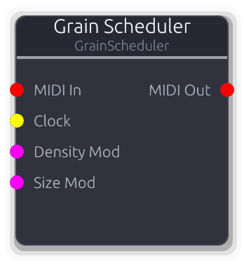
Stochastic MIDI grain triggers for modular granular synthesis
Stochastic MIDI grain trigger generator. Emits overlapping note-on / note-off pairs at a configurable density.
When MIDI In is disconnected, note numbers cycle round-robin through base_note..base_note+Voices-1, mapping to Voice Mixer slots. When MIDI In is connected, held notes form a note pool and the scheduler cycles through those instead -- if the pool is empty no grains fire.
Clock input overrides density: one grain per rising edge. Density and Size Mod CVs are additive to the property values. Jitter randomizes spawn timing; Size Jitter randomizes grain duration; Velocity Jitter randomizes note velocity. In Chord mode all voice slots fire simultaneously per grain with optional stagger spread. If a new grain targets a note that is already active, the old grain is released first to prevent double note-ons.
Properties
| Name | Type | Default | Range | Help |
|---|
Density | Float (Hz) · Knob | 10 | 0.5 – 100 | Grain spawn rate in Hz. Ignored when the Clock input is connected. |
Size | Float (ms) · Knob | 200 | 5 – 500 | Grain duration in milliseconds (time between note-on and note-off). |
Voices | Int · SpinBox | 8 | 1 – 64 | Number of voice slots. Note numbers cycle 0..Voices-1. |
Base Note | Int · SpinBox | 60 | 0 – 127 | MIDI note number offset. Outputs notes base..base+Voices-1. |
Mode | Enum · Dropdown | 0 | Single / Chord | Single: one note per grain, round-robin. Chord: all voices per grain. |
Stagger | Float (ms) · Knob | 5 | 0 – 10 | Time spread across chord voices in Chord mode (ms). Ignored in Single mode. |
Jitter | Float · Knob | 0.1 | 0 – 1 | Timing jitter on grain spawn (randomizes inter-grain interval). |
Size Jitter | Float · Knob | 0.1 | 0 – 1 | Randomization of grain duration. |
Velocity | Float · Knob | 1 | 0 – 1 | Base MIDI velocity for grain triggers (0.0-1.0 maps to 0-127). |
Vel Jitter | Float · Knob | 0 | 0 – 1 | Per-grain velocity randomization. |
Inputs
MIDI In MIDI #0 · required - Held notes define which notes the scheduler cycles through. When disconnected, notes are generated from BaseNote + Voices.
Clock Gate #1 · required - External clock for synced grain density. One grain per rising edge.
Density Mod Control (Norm) #2 · required - Modulates grain spawn rate.
Size Mod Control (Norm) #3 · required - Modulates grain duration.
Outputs
MIDI Out MIDI #0 - Grain triggers as MIDI note-on/note-off events.

Logs port data and passes it through unchanged. Useful for debugging.
Logs signal information to the console and passes data through unchanged. Accepts any port type.
Insert inline to inspect audio levels, control values, MIDI events, gate counts, V/Oct ranges, or data payloads without altering the signal chain. The output port type locks to match the connected input. Audio logs show stereo min/max range; MIDI logs show individual events; empty MIDI buffers are skipped. The node label (if set) prefixes every log line.
Properties
| Name | Type | Default | Range | Help |
|---|
Log Level Logger | Enum · Dropdown | 2 | Trace / Debug / Info / Warn / Error | Tracing log level for output messages (Trace, Debug, Info, Warn, Error). |
Inputs
Input Audio | Control | Control (Norm) | Control (Bipolar) | Control (Freq) | MIDI | Gate | V/Oct | Data(Unknown) | Image #0 · required - Any signal type to log and forward.
Outputs
Output Audio | Control | Control (Norm) | Control (Bipolar) | Control (Freq) | MIDI | Gate | V/Oct | Data(Unknown) | Image #0 - Input data passed through unchanged.
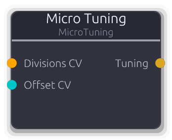
Microtonal tuning - divisions/octave and V/Oct offset with CV modulation
Microtonal tuning configuration source. Outputs a `TuningConfig` on a Data port for downstream pitch calculations.
CV inputs are additive: the Divisions CV value is added to the property value, and the Offset CV value is added to the property value, both clamped to their respective ranges after summing. Standard 12-TET is the default (12 divisions, 0 offset).
Properties
| Name | Type | Default | Range | Help |
|---|
Divisions/Oct | Float · Knob | 12 | 1 – 128 | Equal divisions of the octave (12 = standard tuning). |
V/Oct Offset | Float · Knob | 0 | -10 – 10 | V/Oct offset shifts the keyboard mapping up or down. |
Inputs
Divisions CV Control (Freq) #0 - Modulates divisions/octave (added to property value).
Offset CV Control (Bipolar) #1 - Modulates V/Oct offset (added to property value).
Outputs
Tuning Data(Tuning) #0 - TuningConfig for downstream pitch calculations.
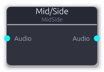
Stereo ↔ mid/side conversion for independent channel processing
Converts between stereo L/R and mid/side representation.
Encode: M = (L+R)/2, S = (L-R)/2. The left channel of the output carries mid, the right carries side. Decode: L = M+S, R = M-S. The left channel of the input is treated as mid, right as side. Use an Encode→processing→Decode chain for mastering-style EQ, compression, or stereo widening on the mid and side independently.
Properties
| Name | Type | Default | Range | Help |
|---|
Mode | Enum · Dropdown | 0 | Encode / Decode | Encode (L/R to M/S) or Decode (M/S to L/R). |
Inputs
Audio Audio #0 · required - Stereo audio: L/R for encoding, M/S for decoding.
Outputs
Audio Audio #0 - Converted stereo audio: M/S from encoding, L/R from decoding.
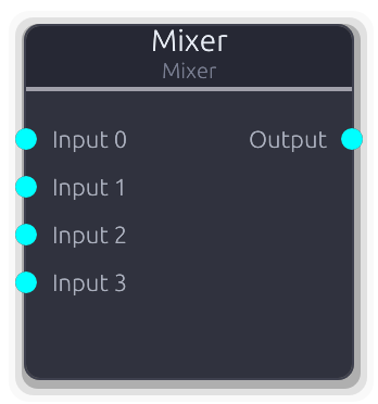
Sums multiple audio inputs with per-input gain and pan control
Sums multiple stereo audio inputs into a single output with per-input gain and constant-power pan controls, plus a master gain stage.
Each input is gained and then panned using a constant-power (sin/cos) law before summing. Pan at -1.0 routes all energy to the left; at 1.0 to the right; at 0.0 the input is centered with equal power in both channels. The per-input gain multiplies the signal before the pan stage, so gain and pan interact: a gained signal is panned, not the other way around. Master gain is applied after all inputs are summed. All gain and pan values are per-sample smoothed to prevent clicks.
Properties
| Name | Type | Default | Range | Help |
|---|
Inputs | Int · Slider | 4 | 1 – 64 | Number of audio input ports (1-64). |
Master Gain | Float · Knob | 1 | 0 – 4 | Output level multiplier applied after all inputs are summed. |
Inputs
Input Audio unbounded - Audio source to mix. Per-input gain and pan are available.
Outputs
Output Audio #0 - Summed and gained stereo mix.
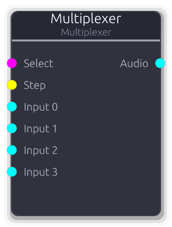
Selects from multiple audio inputs with smooth crossfading
Selects one of N audio inputs and routes it to a single output with smooth crossfading between adjacent channels.
Selection by CV (0.0 = first input, 1.0 = last) or gate stepping. The Select CV overrides the step index when connected. Step gate advances by one on each rising edge; with Wrap enabled, stepping past the last input returns to the first, otherwise it clamps. Crossfade time controls how quickly the smoothed position tracks the target -- at 0 ms transitions are instant. Only connected inputs participate; disconnected slots contribute silence.
Properties
| Name | Type | Default | Range | Help |
|---|
Inputs Routing | Int · Slider | 4 | 1 – 64 | How many audio input ports to create. |
Crossfade Routing | Float (ms) · Slider | 5 | 0 – 1000 | Smoothing duration for position transitions. At 0 ms the switch is instant; longer values create gradual blends. |
Selection Routing | Int · Slider | 0 | 0 – 63 | Current step index (0-based). Updated by the Step gate or set directly. Ignored while the Select CV is connected. |
Wrap Routing | Bool · Toggle | true | | When enabled, the Step gate wraps from the last input back to the first. When off, stepping clamps at the last input. |
Inputs
Select Control (Norm) #0 - Continuous position selector. Fractional values crossfade between adjacent inputs. Overrides the step index when connected.
Step Gate #1 - Rising edge advances to the next input.
Input Audio unbounded - Audio source to select from.
Outputs
Audio Audio #0 - Selected and crossfaded audio output.
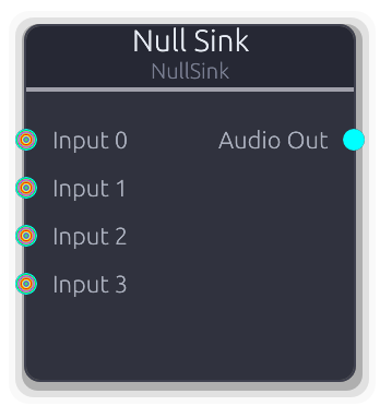
Discards all inputs and outputs silence
Pulls and discards all connected inputs, then outputs silence.
Forces upstream nodes to process in a pull-based graph without routing their output anywhere audible. Accepts any signal type on unbounded inputs. The audio output is always silent zeros. Useful for side-chain triggers, analysis nodes, or any upstream processing chain that needs to run but not be heard.
Properties
| Name | Type | Default | Range | Help |
|---|
Inputs | Int · Slider | 4 | 1 – 64 | Number of input ports (1-64). |
Inputs
Input Audio | Control | Control (Norm) | Control (Bipolar) | Control (Freq) | MIDI | Gate | V/Oct | Data(Unknown) | Image unbounded - Any signal type -- pulled and discarded each buffer.
Outputs
Audio Out Audio #0 - Silent stereo audio (all zeros).
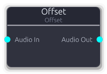
Adds DC bias to audio signal
Adds a constant DC offset to both channels of a stereo audio signal, with per-sample smoothing to prevent clicks.
The same offset value is added to both left and right channels. Useful for shifting bipolar signals to unipolar, biasing control signals routed through the audio bus, or centering waveforms.
Properties
| Name | Type | Default | Range | Help |
|---|
Offset Offset | Float · Slider | 0 | -2 – 2 | DC offset value added to each sample (-2.0--2.0). |
Inputs
Audio In Audio #0 · required - Stereo audio to offset.
Outputs
Audio Out Audio #0 - Offset stereo audio.
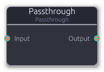
Passes data through unchanged. Accepts any port type.
Copies input data to the output unchanged. Accepts any signal type.
When connected, the port type locks to the first connection's type. If the input is disconnected and the output is audio, the output fills with silence. Useful for testing, as a routing placeholder, or as a type-locking bridge between polymorphic ports.
Inputs
Input Audio | Control | Control (Norm) | Control (Bipolar) | Control (Freq) | MIDI | Gate | V/Oct | Data(Unknown) | Image #0 - Any signal type to pass through.
Outputs
Output Audio | Control | Control (Norm) | Control (Bipolar) | Control (Freq) | MIDI | Gate | V/Oct | Data(Unknown) | Image #0 - Unmodified copy of the input signal.
Randomly passes or blocks gate events with configurable probability
Randomly passes or blocks incoming gate events based on a probability percentage.
Each gate-on event is evaluated independently: at 100% everything passes, at 0% nothing does. Gate-off events pass through only if their corresponding gate-on was allowed, so downstream nodes always see matched on/off pairs.
When PatternLength is >0, random decisions are cached per step position within the pattern cycle. The same step always gets the same pass/block result until the pattern length changes, giving repeatable variation. A Probability Mod CV input overrides the property (0.0--1.0 maps to 0--100%).
Properties
| Name | Type | Default | Range | Help |
|---|
Probability Gate | Float · Slider | 100 | 0 – 100 | Chance each gate-on event passes through (0--100%). |
Pattern Length Gate | Int · SpinBox | 0 | 0 – 64 | When >0, caches random decisions per step for repeatable patterns (0--64). |
Inputs
Gate In Gate #0 · required - Incoming gate events to filter.
Probability Mod Control (Norm) #1 - CV override for probability (0.0--1.0 maps to 0--100%). Replaces the property value when connected.
Outputs
Gate Out Gate #0 - Filtered gate events that passed the probability check.
Quantizes CV to musical scales with optional slew limiting
Snaps V/Oct pitch CV to the nearest note in a musical scale.
Choose a scale type and root note, and the quantizer constrains incoming pitch to valid scale degrees. When the optional Trigger input is connected, quantization only updates on rising edges -- between triggers the output holds the last quantized value. Without Trigger, every sample is quantized continuously.
The Slew property adds portamento between quantized notes. The Gate output fires a rising edge each time the quantized pitch changes to a different note.
Properties
| Name | Type | Default | Range | Help |
|---|
Scale | Enum · Dropdown | 1 | Chromatic / Major / Minor / HarmonicMinor / MelodicMinor / Dorian / Phrygian / Lydian / Mixolydian / Aeolian / Locrian / MajorPentatonic / MinorPentatonic / Blues / WholeTone / Diminished | Musical scale to quantize to (Major, Minor, Pentatonic, etc.). |
Root Note | Enum · Dropdown | 0 | C / C# / D / D# / E / F / F# / G / G# / A / A# / B | Root note of the scale (C through B). |
Range | Float · Slider | 3 | 1 – 5 | Number of octaves the quantizer spans (1--5). |
Slew | Float (ms) · Slider | 0 | 0 – 100 | Portamento time between quantized notes in milliseconds (0--100 ms). |
Inputs
CV In V/Oct #0 · required - V/Oct pitch CV to quantize.
Trigger Gate #1 - Optional trigger -- when connected, quantization only updates on rising edges.
Outputs
CV Out V/Oct #0 - Quantized V/Oct pitch CV snapped to the selected scale.
Gate Out Gate #1 - Trigger pulse on each pitch change.
Half-wave or full-wave rectification for audio and control signals
Rectifies audio or control signals. Both paths operate independently and simultaneously when both inputs are connected.
Full-wave mode applies abs() to each sample, folding the negative half upward and doubling the perceived frequency (octave-up effect on audio). Half-wave mode applies max(0, x), clipping negative values to zero and adding odd harmonics. The control output type is ControlNorm (>= 0) regardless of mode, effectively converting bipolar to unipolar.
Properties
| Name | Type | Default | Range | Help |
|---|
Mode | Enum · Dropdown | 0 | Full / Half | Full-wave (abs) or Half-wave (clip negatives to zero). |
Inputs
Audio Audio #0 - Stereo audio to rectify.
Control Control (Bipolar) #1 - Bipolar control signal to rectify.
Outputs
Audio Audio #0 - Rectified stereo audio.
Control Control (Norm) #1 - Rectified control value (always >= 0).
Gate-triggered sample and hold with glide
Captures the input signal on each gate rising edge and holds that value until the next trigger.
The input audio is mono-downmixed at the sample where the rising edge occurs. The held value is linearly mapped through the OutputMin/OutputMax range (value * (max - min) + min). When glide is non-zero, transitions between held values use an ease-out curve over the glide duration. Gate state is tracked per sample for sample-accurate triggering.
Properties
| Name | Type | Default | Range | Help |
|---|
Glide Time | Float (ms) · Slider | 0 | 0 – 1000 | Transition time between held values. Zero for instant steps; non-zero applies an ease-out interpolation. |
Output Min | Float · Slider | 0 | -1 – 1 | Lower bound of the output mapping. The held value is scaled as value * (max - min) + min. |
Output Max | Float · Slider | 1 | -1 – 1 | Upper bound of the output mapping. |
Inputs
Signal Audio #0 · required - Audio to sample from. Mono-downmixed at the exact sample where the gate rising edge occurs.
Gate In Gate #1 · required - Each rising edge captures a new value from Signal. Gate state is tracked per sample for sample-accurate triggering.
Outputs
Output Audio #0 - Held value as mono-to-stereo audio, mapped through the output range, with glide applied if non-zero.
Envelope follower with gate output - trigger events from audio amplitude
Tracks the amplitude envelope of an audio signal and emits gate events when the level crosses a threshold.
The envelope follower uses asymmetric one-pole smoothing: attack coefficient tracks rising amplitude, release coefficient tracks falling amplitude. The mono-downmixed absolute value is fed into the follower per sample. A Schmitt trigger with configurable hysteresis converts the envelope to a gate: the gate turns on when the envelope exceeds threshold + hysteresis/2, and off when it drops below threshold - hysteresis/2. Gate edges are emitted at sample-accurate offsets. The Envelope output provides the smoothed amplitude as a normalized 0--1 control value.
Properties
| Name | Type | Default | Range | Help |
|---|
Threshold | Float · LogSlider | 0.1 | 0.001 – 1 | Envelope level that triggers a gate-on event (0.001--1.0). |
Hysteresis | Float · Knob | 0.05 | 0 – 0.3 | Dead-band width to prevent chattering near the threshold (0.0--0.3). |
Attack | Float (ms) · Slider | 1 | 0.1 – 50 | Envelope rise time in milliseconds (0.1--50 ms). |
Release | Float (ms) · Slider | 50 | 1 – 500 | Envelope decay time in milliseconds (1--500 ms). |
Inputs
Audio Audio #0 · required - Audio signal to track.
Outputs
Gate Gate #0 - High when envelope exceeds threshold, low when it drops below.
Envelope Control (Norm) #1 - Smoothed amplitude envelope as normalized CV (0.0--1.0).
Two-input audio math: add, subtract, multiply (ring mod), min, max, crossfade
Two-input math on stereo audio signals. Add layers together, subtract for sidechain ducking, multiply for ring modulation, or crossfade between A and B with a mix knob.
Disconnected inputs contribute silence (zero). In Crossfade mode, 0.0 = all A, 1.0 = all B, with per-sample smoothing on the mix. A Mix Mod CV overrides the property value and is fed into the smoother. The smoother advances even when not in Crossfade mode to stay in sync, so switching modes mid-stream is seamless.
Properties
| Name | Type | Default | Range | Help |
|---|
Operation Math | Enum · Dropdown | 0 | Add / Subtract / Multiply / Min / Max / Crossfade | Math operation (Add, Subtract, Multiply, Min, Max, Crossfade). |
Mix Math | Float · Slider | 0.5 | 0 – 1 | Crossfade balance. Only audible in Crossfade mode. |
Inputs
Input A Audio #0 · required - First audio operand.
Input B Audio #1 - Second audio operand. Defaults to silence when disconnected.
Mix Mod Control (Norm) #2 - CV modulation of the crossfade mix (0.0--1.0).
Outputs
Audio Out Audio #0 - Result of the selected math operation.
Duplicates audio signal to multiple outputs with per-output gain control
Duplicates a single stereo audio input to multiple outputs with independent per-output gain control.
At unity gain with a settled smoother, outputs share the input buffer via Arc clone (zero-copy). When gain differs from unity or the smoother is still transitioning, a per-sample copy with gain is performed. Use for parallel processing chains, dry/wet mixing, or multi-destination routing.
Properties
| Name | Type | Default | Range | Help |
|---|
Outputs | Int · Slider | 4 | 1 – 64 | Number of audio output ports (1-64). |
Inputs
Audio In Audio #0 · required - Stereo audio signal to duplicate.
Outputs
Output Audio unbounded - Copy of the input audio, with per-output gain.
Pan and mix up to two audio inputs with independent stereo placement
Pans and mixes up to two stereo audio inputs with independent pan and width controls per channel into a single stereo output.
Pan uses constant-power (sin/cos) placement. Width crossfades between full stereo (1.0) and collapsed mono (0.0) by blending opposite channels. Both channels are summed into the output, so with two sources you get a stereo mix. CV modulation on all four parameters overrides the property values when connected. All parameters are per-sample smoothed. Unconnected inputs contribute nothing, but their smoothers still advance to stay in sync.
Properties
| Name | Type | Default | Range | Help |
|---|
Pan A | Float · Knob | 0 | -1 – 1 | Stereo position of input A (-1.0 left, 0.0 center, 1.0 right). |
Width A | Float · Knob | 1 | 0 – 1 | Stereo width of input A (0.0 = mono, 1.0 = full stereo). |
Pan B | Float · Knob | 0 | -1 – 1 | Stereo position of input B (-1.0 left, 0.0 center, 1.0 right). |
Width B | Float · Knob | 1 | 0 – 1 | Stereo width of input B (0.0 = mono, 1.0 = full stereo). |
Inputs
Audio A Audio #0 - First stereo audio source.
Pan A Mod Control (Bipolar) #1 - CV modulation for Pan A (-1.0--1.0).
Width A Mod Control (Norm) #2 - CV modulation for Width A (0.0--1.0).
Audio B Audio #3 - Second stereo audio source.
Pan B Mod Control (Bipolar) #4 - CV modulation for Pan B (-1.0--1.0).
Width B Mod Control (Norm) #5 - CV modulation for Width B (0.0--1.0).
Outputs
Audio Out Audio #0 - Combined stereo mix of A and B with panning applied.
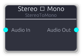
Downmix stereo audio to mono (L+R average, output as dual-mono stereo)
Downmixes stereo audio to mono by averaging L and R. The output is still a stereo frame (both channels identical) since the audio bus is always stereo. Useful before processing that expects a centered mono signal.
Inputs
Audio In Audio #0 · required - Stereo audio to downmix.
Outputs
Audio Out Audio #0 - Dual-mono stereo audio (L = R = average).
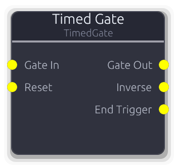
Fixed-duration gate with transport or wall-clock trigger
Fixed-duration gate generator with two independent timing modes.
In WallClock mode, a rising edge on Gate In starts the cycle: optional delay, then the gate opens for the configured duration. A retrigger during the active phase restarts the cycle. The Reset input forces the gate closed and returns to idle.
In Transport mode, the gate auto-fires when the transport reaches the Offset bar. Stopping the transport closes the gate and re-arms the trigger; starting again re-evaluates the offset. Duration, delay, and gap are specified in bars and scale with tempo.
Both modes support repeat (Off, Infinite, or a fixed Count) with an optional gap between cycles. Three outputs: the gate itself, an inverted copy, and a one-sample end-trigger pulse when the active phase closes.
Properties
| Name | Type | Default | Range | Help |
|---|
Mode | Enum · Dropdown | 0 | WallClock / Transport | Trigger mode: Transport (bar-aligned) or WallClock (ms-precision). |
Offset | Int · SpinBox | 0 | 0 – 9999 | Bar at which the gate first opens (transport mode). |
Bars | Int · SpinBox | 1 | 1 – 9999 | How many bars the gate stays open (transport mode). |
Delay | Int · SpinBox | 0 | 0 – 9999 | Bars to wait after offset before opening (transport mode). |
Gap | Int · SpinBox | 0 | 0 – 9999 | Bars of silence between repeat cycles (transport mode). |
Duration | Int (ms) · SpinBox | 500 | 1 – 65535 | Gate duration in milliseconds (wall-clock mode). |
Delay | Int (ms) · SpinBox | 0 | 0 – 65535 | Milliseconds to wait after trigger before opening (wall-clock mode). |
Gap | Int (ms) · SpinBox | 0 | 0 – 65535 | Milliseconds of silence between repeat cycles (wall-clock mode). |
Repeat | Enum · Dropdown | 0 | Off / Infinite / Count | Whether the gate cycles after closing. |
Count | Int · SpinBox | 1 | 1 – 9999 | Number of repeat cycles (visible when Repeat == Count). |
Inputs
Gate In Gate #0 · required - Trigger source (WallClock mode only). Rising edge starts or retriggers the cycle. Ignored in Transport mode.
Reset Gate #1 · required - Forces the gate closed and resets all state to idle (WallClock mode only). Ignored in Transport mode.
Outputs
Gate Out Gate #0 - Fixed-duration gate signal.
Inverse Gate #1 - Inverted gate -- HIGH when Gate Out is LOW.
End Trigger Gate #2 - One-sample pulse when the active phase ends. Fires before the gap or next cycle begins -- useful for chaining.
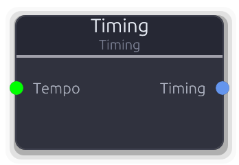
Timing source - BPM, time signature, and key signature
Outputs structured timing metadata (BPM, time signature, key signature) as a `TimingData` value on a Data port.
When the Tempo input is connected, its value replaces the BPM property (clamped 1--999). Time signature and key signature always come from the properties. The Beat Unit property is an encoded power-of-two exponent (0=1, 1=2, 2=4, 3=8, 4=16, 5=32).
Properties
| Name | Type | Default | Range | Help |
|---|
BPM | Float · SpinBox | 120 | 1 – 999 | |
Beats/Bar | Int · SpinBox | 4 | 1 – 32 | |
Beat Unit | Int · SpinBox | 2 | 0 – 5 | |
Key (sharps/flats) | Int · SpinBox | 0 | -7 – 7 | |
Minor | Bool · Checkbox | false | | |
Inputs
Tempo Control #0 - Replaces the BPM property with the signal value (clamped 1--999).
Outputs
Timing Data(Timing) #0 - Structured timing metadata.
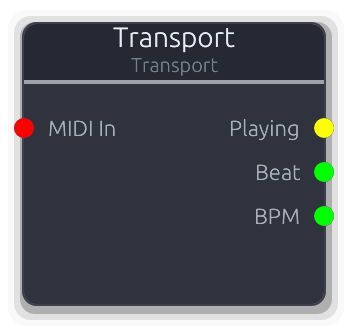
Outputs transport state: playing gate, beat position, and tempo
Exposes the global transport state as patchable signals and optionally accepts MIDI input for external transport control.
Three outputs: Playing (gate high while transport plays, with edge events on transitions), Beat (unbounded Control with the current beat position), and BPM (unbounded Control with the current tempo). The node always processes even when no outputs are connected, to ensure MIDI transport commands are captured.
When a MIDI input is connected, system real-time Start/Continue messages trigger Play, Stop messages trigger Stop, and configurable CC numbers map to play, stop, and master volume. CC values >0 trigger the action; volume maps 0--127 to 0.0--1.0.
Properties
| Name | Type | Default | Range | Help |
|---|
Play CC | Int · SpinBox | 115 | -1 – 127 | MIDI CC number that triggers play. Set to -1 to disable. |
Stop CC | Int · SpinBox | 116 | -1 – 127 | MIDI CC number that triggers stop. Set to -1 to disable. |
Volume CC | Int · SpinBox | 79 | -1 – 127 | MIDI CC number for master volume. Maps CC value 0--127 to volume 0.0--1.0. Set to -1 to disable. |
Inputs
MIDI In MIDI #0 · required - MIDI input for external transport control. System RT messages and configured CCs are translated to transport commands.
Outputs
Playing Gate #0 - Gate high while transport is playing, low when paused.
Beat Control #1 - Current beat position as an unbounded control value.
BPM Control #2 - Current tempo in beats per minute as an unbounded control value.
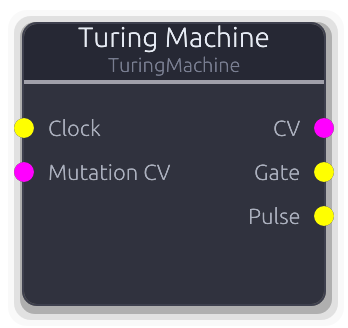
Shift register sequencer with mutation probability for evolving patterns
Shift register sequencer that generates looping CV and gate patterns which evolve over time via a mutation probability knob.
On each clock rising edge the register shifts right by one bit. The LSB wraps to the MSB position, with a configurable chance of being flipped. At 0% mutation the sequence repeats perfectly; at 100% the output is fully random. The CV output is the full register value normalized to 0.0--1.0. The Gate output reflects the MSB. The Pulse output fires a one-sample trigger on every clock step regardless of register content. The register initializes with random bits on the first clock edge.
Properties
| Name | Type | Default | Range | Help |
|---|
Length Sequence | Int · SpinBox | 8 | 2 – 32 | Active register length in bits (2–32). |
Mutation Sequence | Float (%) · Slider | 0 | 0 – 100 | Probability of flipping the recycled bit each step (0–100%). |
Inputs
Clock Gate #0 · required - Clock input - each rising edge advances the register.
Mutation CV Control (Norm) #1 · required - CV control over mutation probability (0.0--1.0 maps to 0--100%). Overrides the Mutation property when connected.
Outputs
CV Control (Norm) #0 - Full register value normalized to 0.0--1.0. Updates once per clock step and holds between clocks.
Gate Gate #1 - High when MSB of register is 1.
Pulse Gate #2 - Trigger pulse on every clock step.
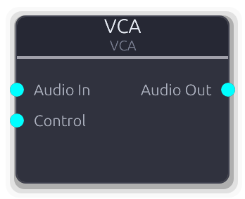
Voltage controlled amplifier for audio-rate modulation
Voltage-controlled amplifier -- multiplies two stereo audio signals sample-by-sample, channel-by-channel.
Both inputs are Audio type (not Control), enabling true stereo audio-rate modulation. Wire an envelope, LFO, or any audio source into the Control input for amplitude shaping, tremolo, or ring modulation. Both inputs are required -- the node produces nothing if either is disconnected.
Inputs
Audio In Audio #0 · required - Audio signal to modulate.
Control Audio #1 · required - Audio-rate modulator (envelope, LFO, or other audio). Multiplied channel-by-channel with Audio In.
Outputs
Audio Out Audio #0 - Audio multiplied by the control signal.
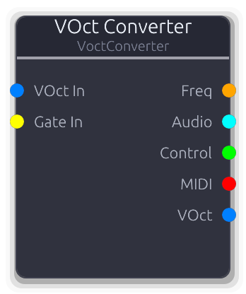
Converts VOct pitch CV to multiple output types simultaneously
Converts V/Oct pitch CV to multiple output formats simultaneously.
Freq output: reference_freq * 2^voct. Audio output: dual-mono stereo from the V/Oct buffer values (not frequency). Control output: raw V/Oct value. VOct output: pass-through of the input buffer. MIDI output: converts the first sample's V/Oct to a note number (voct * 12 + reference_note, rounded) and emits note-on / note-off events driven by the Gate input. Without a Gate input, no MIDI events are generated. Note changes without a gate re-trigger do not emit new note-on events.
Properties
| Name | Type | Default | Range | Help |
|---|
Reference Note Main | Int · SpinBox | 60 | 0 – 127 | MIDI note number at 0V. Used for both the frequency calculation reference and the V/Oct-to-MIDI note mapping. |
Inputs
VOct In V/Oct #0 · required - V/Oct pitch CV to convert.
Gate In Gate #1 - Drives MIDI note-on/note-off generation. Without this input connected, the MIDI output stays empty.
Outputs
Freq Control (Freq) #0 - Pitch as frequency in Hz.
Audio Audio #1 - Dual-mono stereo audio from V/Oct values.
Control Control #2 - Raw V/Oct value as a control signal.
MIDI MIDI #3 - MIDI note events generated from V/Oct + gate.
VOct V/Oct #4 - V/Oct pass-through.
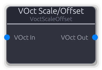
Scale and offset VOct pitch CV. Useful for creating intervals, harmonies, and creative pitch effects.
Multiplies and offsets V/Oct pitch CV per sample: output = input * Scale + Offset.
Negative Scale inverts pitch intervals. Scale of 2.0 doubles intervals (octave becomes two octaves). Offset shifts the entire pitch up or down in V/Oct units (1.0 = one octave). Useful for creating harmonies, inversions, and creative pitch effects.
Properties
| Name | Type | Default | Range | Help |
|---|
Scale Transform | Float · Slider | 1 | -4 – 4 | Multiplier applied to V/Oct value (-4.0--4.0). Negative inverts pitch. |
Offset Transform | Float · Slider | 0 | -4 – 4 | Constant added to V/Oct after scaling (-4.0--4.0 octaves). |
Inputs
VOct In V/Oct #0 · required - V/Oct pitch CV to transform.
Outputs
VOct Out V/Oct #0 - Scaled and offset V/Oct pitch CV.
Smooth VOct pitch transitions with configurable slew rate. Creates portamento/glide effects between notes.
Rate-limits V/Oct pitch transitions for portamento and glide effects. Operates at audio rate (per sample).
Rise and Fall times override SlewTime when set above zero. If both are zero, SlewTime is used for both directions. A Slew Mod CV (0.0--1.0) scales the effective slew time: at 0.0 transitions are instant, at 1.0 the full time is used. The maximum change per sample is 1/(slew_time * sample_rate) V/Oct. On the first sample the output jumps to the input with no slew.
Properties
| Name | Type | Default | Range | Help |
|---|
Slew Time Timing | Float · Slider | 0.1 | 0 – 10 | Base glide time in seconds (0--10 s). Used when rise/fall are zero. |
Rise Time Timing | Float · Slider | 0 | 0 – 10 | Upward glide time in seconds (0--10 s). Overrides SlewTime when >0. |
Fall Time Timing | Float · Slider | 0 | 0 – 10 | Downward glide time in seconds (0--10 s). Overrides SlewTime when >0. |
Inputs
VOct In V/Oct #0 · required - V/Oct pitch CV to smooth.
Slew Mod Control (Norm) #1 - CV scaling of slew time (0.0 = instant, 1.0 = full slew time).
Outputs
VOct Out V/Oct #0 - Slew-limited V/Oct output.
Transpose VOct pitch CV by semitones, octaves, and cents.
Shifts V/Oct pitch CV by semitones, octaves, and cents.
All three offsets are summed into a single V/Oct shift: semitones/12 + octaves + cents/1200. The combined offset is added to every sample in the input buffer. Use for fixed transpositions, octave layering, or fine-tuning.
Properties
| Name | Type | Default | Range | Help |
|---|
Semitones Transpose | Int · Slider | 0 | -48 – 48 | Transpose in semitones (-48--48). |
Octaves Transpose | Int · Slider | 0 | -4 – 4 | Transpose in whole octaves (-4--4). |
Cents Transpose | Int · Slider | 0 | -100 – 100 | Fine-tuning offset in cents (-100--100). |
Inputs
VOct In V/Oct #0 · required - V/Oct pitch CV to transpose.
Outputs
VOct Out V/Oct #0 - Transposed V/Oct pitch CV.